garage door indicator

Indicator For Forgetful-Minded Garage Door Users

[Gareth] had a friend who regularly forgot to close his garage door after parking his car and heading inside. Since [Gareth] was familiar with basic electronics and an overall good pal, he offered to make a device that would indicate whether the garage door was open or not.

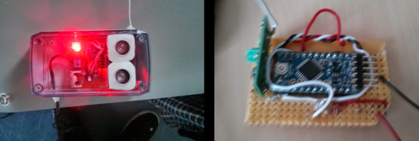
The project starts off simple with an Arduino and ultrasonic distance sensor. Both are mounted to the ceiling of the garage with the ultrasonic sensor pointed down. When the garage door is open, the sensor outputs a shorter distance measurement than when the garage door is closed.

Now that the system knows when the door is open or closed, the next part was sending a signal inside the house. He could have run a wire up through the house walls to an LED indicator but decided to go wireless with a 433mhz transmitter. There is a second Arduino inside equipped with a 433mhz receiver. When the garage door is open, the Arduino inside the house flashes an LED reminding the forgetful occupant to close the door.

[Gareth] made all his code for both the sensor/transmitter and the receiver available on his site for anyone interested in making something similar.

Upgrading A Microsoft Surface To A 1 TB SSD

The Microsoft Surface Pro 3 is a neat little tablet, and with an i7 processor, a decent-resolution display, and running a full Windows 8.1 Pro, it’s the closest you’re going to get to a desktop in tablet format. Upgrading the Surface Pro 3, on the other hand, is nigh impossible. iFixit destroyed the display in their teardown, as did CNET. [Jorge] wanted to upgrade his Surface Pro 3 with a 1 TB SSD, and where there’s a will there’s a way. In this case, a very precise application of advanced Dremel technology.

Taking a Surface Pro 3 apart the traditional way with heat guns, spudgers, and a vast array of screwdrivers obviously wasn’t going to work. Instead, [Jorge] thought laterally; the mSSD is tucked away behind some plastic that is normally hidden by the small kickstand integrated into the Surface. If [Jorge] could cut a hole in the case to reveal the mSSD, the resulting patch hole would be completely invisible most of the time. And so enters the Dremel.

By taking some teardown pictures of the Surface Pro 3, printing them out to scale, and aligning them to the device he had in his hand, [Jorge] had a very, very good idea of where to make the incision. A Dremel with a carbide bit was brought out to cut into the metal, and after a few nerve-wracking minutes the SSD was exposed.

The only remaining task was to clone the old drive onto the new one, stuff it back in the Surface, and patch everything up. [Jorge] is using some cardboard and foam, but a sticker would do just as well. Remember, this mod is only visible when the Surface kickstand is deployed, so it doesn’t have to look spectacular.

Thanks [fridgefire] and [Neolker] for sending this in.

Adding PID Control To A Non-Adjustable Iron

Do remember your first soldering iron? We do. It plugged into the wall, and had no way to adjust the temperature. Most people call these kind of irons “fire starters.” Not only are they potentially unsafe (mainly because of the inadequate stand they come with) they can be hard to use, slow to heat up, and you never know what temperature you are soldering at.

[Mike Doughty] wondered if you could hack a cheap iron to be temperature controlled. He began by taking apart an iron, and adding a K-type thermocouple to the mica heating element with the help of a fiberglass sleeve. After a few tries at fitting and finding the right placement for the thermocouple, he then reassembled the iron, and attached everything to an off-the-shelf industrial PID controller.

Not one to trust that everything was working, [Mike] began to test the iron. He used a Hakko FG-100 soldering iron tip thermometer to measure the “real” temperature of tip, and compared it to the value the K-type thermocouple was reporting it to be. The results were fairly impressive (as seen in the video after the break). Only about 10 degrees out. Not too shabby.

He concluded that although it did work, it wasn’t a replacement for a high quality soldering station. We suspect the real problem with this idea is that the mica heating element is way to slow to respond to any thermal load that the tip is given (but then neither did the unmodified iron.) If you’re interested in hacking together your own soldering station, you might be interested in the open source soldering iron driver.

[via Dangerousprototypes]

Continue reading “Adding PID Control To A Non-Adjustable Iron”

Hackaday Retro Edition: TRS Wiki

1977 was a special year for computing history; this year saw the release of the 8085 following the release of the Z80 a year before. Three companies would launch their first true production computers in 1977: Apple released the Apple II, Commodore the PET 2001, and Tandy / Radio Shack the TRS-80 Model I. These were all incredibly limited machines, but at least one of them can still be used to browse Wikipedia.

[Pete]’s TRSWiki is a Wikipedia client for the TRS-80 Model I that is able to look up millions of articles in only uppercase characters, and low resolution (128×48) graphics. It’s doing this over Ethernet with a very cool Model I System Expander (MISE) that brings the lowly Trash-80 into the modern era.

The MISE is capable of booting from CF cards, driving an SVGA display and connecting to 10/100 Ethernet. Connecting to the Internet over Ethernet is one thing, but requesting and loading a web page is another thing entirely. There’s not much chance of large images or gigantic walls of text fitting in the TRS-80’s RAM, so [Pete] is using a proxy server on an Amazon Web Services box. This proxy is written in Java, but the code running on the TRS-80 is written entirely in Z80 assembly; not bad for [Pete]’s first project in Z80 assembly.


vt100normal The Hackaday Retro Edition is our celebration of old computers doing something modern, in most cases loading the old, no CSS or Javascript version of our site.

If you have an old computer you’d like featured, just load up the retro site, snap some pictures, have them developed, and send them in.

Retrotechtacular: Radar Jamming

It’s been said that the best defense is a good offense. When aloft and en route to deliver a harmful payload to the enemy, the best defense is to plan your approach and your exit carefully, and to interfere with their methods of detection. If they can’t find you, they can’t shoot you.

As of May 1962, the United States military was using three major classifications of radar jamming technology as described in this week’s film: the AN/ALQ-35 multiple target repeater, the AN/ALQ-55 communications link disrupter, and the AN/ALQ-41 and -51 track breakers. The most important role of these pieces of equipment is to buy time, a precious resource in all kinds of warfare.

The AN/ALQ-35 target repeater consists of a tuner, pulse generator, transmitter, and control panel working in concert to display multiple false positives on the enemy’s PPI scopes. The unit receives the incoming enemy pulse, amplifies it greatly, repeats it, and sends them back with random delays.

The AN/ALQ-55 comm disrupter operates in the 100-210MHz band. It distinguishes the threatening enemy communication bands from those of beacons and civilians, evaluates them, and jams them with a signal that’s non-continuous, which helps avoid detection.

Finally, the AN/ALQ-41 and -51 track breakers are designed to break enemy lock-on and to give false information. It provides simultaneous protection against pulse ranging, FM-CW, conical, and monopulse radar in different ways, based on each method’s angle and range.

Continue reading “Retrotechtacular: Radar Jamming”

DOTS Uses Paint To Control Raspberry Pi 2

Two tables down from us at SXSW Create the Raspberry Pi foundation had a steady stream of kids playing Minecraft on Raspberry Pi, and picking up paint brushes. The painting activity was driven by a board they spun for the event that used conductive paint to control the Raspberry Pi 2.

rear-of-the-raspberry-pi-2The board uses the HAT form factor which it a fancy name for a shield (also a clever one as it stands for “Hardware Attached on Top”). You can see the back side of the board in this image. It utilizes an extremely low-profile surface mount pin socket.

The front side exposes several circular pads of copper which build up a “connect-the-dots” game that is played by painting conductive ink on the surface. This results in an airplane being pained on the board, as well as displayed on the computer. There is a set of pads that allow the user to select what color is painted on the monitor.

We like this as a different approach to education. Kids are more than used to tapping on a touchscreen, clicking a mouse, or pounding a keyboard. But conductive ink provides several learning opportunities; the paint simply connects the inner circle with the outer circle; one of these circles is the same on every single dot (ground); anything that connects these two parts of the dot together will result in input for the computer. Great stuff!

The foundation is taking the boards to Maker Faire Bay Area next month so stop by to see these in action. You can read about the production process for the DOTS board on the Raspberry Pi website. They’re giving away a few boards to software developers who want contribute to the project. And our video interview with [Matt Richardson] is found after the break.

Continue reading “DOTS Uses Paint To Control Raspberry Pi 2”

Header of the Project Byzantium website

Meshing Pis With Project Byzantium

If internet service providers go down, how are we going to get our devices to communicate? Project Byzantium aims to create an “ad-hoc wireless mesh networking for the zombie apocalypse.” It’s a live Linux distribution that makes it easy to join a secure mesh network.

[B1tsh1fter] has put together a set of hardware for running Byzantium on Pis in emergency situations. A Raspberry Pi 2 acts as a mesh node, using a powerful USB WiFi adapter for networking. Options are provided for backup power, including a solar charger and a supercapacitor based solution.

The Pi runs a standard Raspbian install, but uses packages from the ByzPi repository. This provides a single script that gets a Byzantium node up and running on the Pi. In the background, OLSR is used to route packets through the mesh network, so that nodes can communicate without relying on a single link.

The project has a ways to go, but the Raspberry Pi based setup makes it cheap and easy to get a wide area network up and running without relying on a single authority.