When you look at the current methods of scanning 2D and 3D objects available today, you’re basically looking at an imaging process. Either you take a picture of a 2D object, or you grab a blob of point clouds with a 3D scanner and make a 3D object that way. It wasn’t always like this – real, hardware 3D digitizers were used all the way back in the 70s, and touch probes are standard equipment on high-end CNC machines.
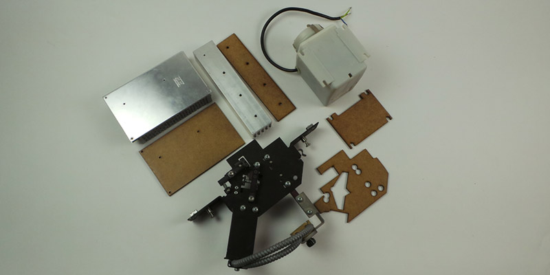
[Nikolaj Møbius] needed a way to record points in physical space, and not wanting to deal with the problems of images, he made an open source DIY digitizer. It’s basically a laser cut arm with rotary encoders at each joint. By reading the rotary encoders with an Arduino, [Nikolaj] can digitize a few points on a workpiece – just enough to make a bracket, or find the critical dimensions of a part.
It’s a great tool for when you need a little more information than a set of calipers can provide, and a great example of some ancient tech made useful again.


cool, a rotary encoder for the ground plate could add some flexibility for measuring complex objects
Given the limitations of this (resolution of the arm, reach area of the arm), I wonder if it would be better* to create something more akin to the Valve Lighthouse (http://hackaday.com/2015/05/18/an-introduction-to-valves-tracking-hardware/) and, rather than gather angles for the arms, you extract the angles against a reference stick (which allows you to calculate where the point is).
*for some aspects of better obviously
True, but I think the whole point is that this is a budget hack for people who don’t have access to scanning IR lasers. Very ingenious! One application that comes to mind is for sculpting foam cases for protecting complex objects. If you can roughly model a shape, you could have a cnc machine route out the reverse from a block of foam, so you could have snugly-fitted protective case. Shipping applications in general would benefit from knowing what size box you need. (How many foam peanuts, etc…)
I guess it falls down to what is easily accessed (the encoder is already being sourced from ebay and a scanned line could be hacked from a variety of sources) and the final intent with what the 3D input is being used for.
For some of the applications, it could be easier to go down the point-cloud route via a scanning beam (gives you basic volumetric data quickly) but the nice thing with this manual contact route is that you (the fleshy human) can more readily discern which data is of importance (picking out vertices, mounting holes, fiducial markers) before it is lost any ‘noisy cloud’.
One thing that I think this arm was missing is a button on the arm to say “capture this point” (to save having to go back to the keyboard and lose your focus on the object)
Adding the button with that sloppy arm, might induce lots of noise. (not that it would be good for a more solidly built arm.
I’ve been wanting one of those to digitize things for a long time, but the cheapest one avaliable is like 1500€ and way more clumsy. At least with this, I can build the hardware as good (or bad) as I want. XD
Microswitch on the end would do the same.
It wouldn’t. It makes this device like having thumb in middle of your hand.
I’m going to build this, and maybe rotating table (ordered 4 encoders). I’m probably making the base with my own design so it can hold the arduino board and the base has also a buttons for taking a point sample or start / stop “line” command. The keyboard method isn’t too bad, usually you can drag your keyboard enough close to press sample buttons..
I think this is so awesome! It would save me so much time with building enclosures and fixings.
very nice indeed. It would be cool to see one done with a gantry system like the older brown and sharp setups.
I WANT ONE NOW! :D
“PDF vector file. The Z axis is simply ignored in the output. Since the system actually records in a 3D space it is possible to export a 3D object for post processing. This is mainly a matter of implementing a another export method.” -From Source
Universal_3D aka U3D seems like a good idea to support 3D in PDF. wikipedia.org/wiki/IText and wikipedia.org/wiki/Jreality might even have drop in candidate libraries.
If any one is interested, there is a decent set of tools available: wikipedia.org/wiki/FreeCAD wikipedia.org/wiki/MeshLab and wikipedia.org/wiki/DAZ_Studio (Now Free) says it handles PDF’s with U3D.
However, the comparison lists shows there aren’t many opensource/Free CAD progs that handle this format, so maybe just get comfortable with the above tools export it to collada.org or .stl ? Drifting down the rabbithole of CAM/CNC the amount of formats and languages is staggering; wiki.linuxcnc.org/cgi-bin/wiki.pl?LinuxCNCKnowledgeBase, opencam.sourceforge.net/ pycam.sourceforge.net/ seem like good places to start.
Regarding the first scan we could use the software to re-reference 3 (or more) points from the initial scan plane as markers. THEN we could and place the object on a different orientation and re-mark the same contact/reference points to combine both scans and indicate the new alignment?
Oh, I just realized if we add 2 contact points at the rings for the base on that sits flush against base plate, the sketch could use 1(2?) more IO (1 circuit closed, 2 circuit open) saying “I am horizontal”. Add a discrete hinge, a small metal shelving L, & a piece of fixed length wire “key” (screw, wire coat-hanger, eye-hook, windshield wiper spine) to lock it in place at 90 degrees making the 2nd contact (1 circuit open, 2 circuit closed) with the sketch saying “I am now vertical”. Might be viable.
The code already handles 4 axis (turntable). I updated the rep. with the drawings for the turntable.
Hey Dzl. :)
Yeah. I wasn’t extrapolating enough on my thoughts. I meant is it possible the software to handle turning the object upside down / on it’s side and capture more detail?
I have the commercial version of this (6ft romer arm with a hard probe), and have been inside it to repair it, and they do a few nice tricks which might be worth mentioning.
They put a encoder and a small computer standalone at each encoder and pass data between the encoder positions via a serial network, this lets the arm have 360 rotation with no hard stops but is only passing serial data and voltages via slip rings rather than rotating sensitive encoder wires which are prone to breaking.
It also has some buttons on the end of the arm to tell the system to sample a point (and so it can be used as a 3d mouse to control the software remote). Because the buttons connect the end encoder processing board, it doesnt increase noise over a distance.
The arm I have uses carbon fibre tubes for the spans because its dimensionally a lot more stable than aluminum. While your handling the arm your body heat causes expansion and in a vector sum calculation like this it makes for a amplified error.
For setting up the arm, its a $2000 back to romer to do, and they have a jig they put the arm in to hold all the joints in a certain position, then zero off the encoders and apply the offsets to a config file. That way your not having to make microscopic alterations to arm spindle connections to the encoders, you can get them near, then set up in your software to compensate. Im still investigating this as support for my arm has been discontinued as its now declared obsolete and my arm needs re-alignment as it has a slight inaccuracy outside spec so I have to make all the stuff myself to replicate it.
Software, good luck with finding something that can take point co-ordinates and pull them into cad. The arm itself uses a daemon called winRDS which is proprietory which takes in strings from the arm, applies the compensation factors and spits out co-ordinates to programs with a api that takes them. Ie geomagic, powerinspect, pcdmis etc. And these are ALL horribly expensive.
The main problem is going to be verification and calibration of the resulting arm, I have tooling calibration spheres, a length standard and a ring master. When I measure the ring master my arm is within spec, but if I place the ball probe in a socket and rotate all the joints through their full motions the point moves, indiciating a joint is out of calibration causing a error in the vectorial sum.
Id rip the proprietory innards out and remake it with open stuff if it ever became possible as most of the problems I have encountered have been because of the locked up proprietory nature of the inner workings. I was pondering linuxcnc with the kinematics as a daemon but will watch activity in the arduino world too.
To reply to myself to clarify, I would think you need to have 6 degrees of freedom at least to measure 3d points on a object if that is the expanded idea. This involves two joints which rotate, one on the wrist and one on the elbow and a rotary on the base. I know this is nowhere near that level, but I can see people thinking about replicating it and expanding it hence my long comment.
The linuxcnc stuff I was thinking of the robot arm kinematics setups, after all a portable cmm is a robot arm with no motors in it but so far thats all I have done, think.
That is what I wanted to really get at, In the video it shows them doing the calibration, measuring/marking the hole points, even doing a little zig zag on a piece of equipment on the bench area. The 3D diagram they have shows them rotating the object on screen. Hence my interest on saying ‘can we collect/record more info?’ There are literally 1000’s of tractors and machinery that no longer have parts being made for them.
Fine, we can do a green sand mold or lost wax process to pour new parts but they wont maintain functionality more then 100 hours or less, unless they are cleaned up and somehow annealed (and throw in some Vanadium sputtering) to handle the stress.
All and all; DZL and fablab.ruc have show cased something really wonderful. Please don’t stop [DZL].
I fully encourage them further AND farther in their hardware and software project.
“You wouldn’t download a village…” Yes, Yes I would. http://opensourceecology.org/gvcs/
[McFluffy] I hate to say it but if you already have the experience, there is very little to any pre-packaged works right out of the box software for what you have. If you are a freelancer or in-between work, You will have to make a PROPER 1-3 month 8 hours a day project to re-furbishing the tech. You might even be able to get folks from the local hacker space to stop by and do some logic pirate/bus pirate/Open Logic scanner treatment on reverse engineering how the system intercommunicates. And if you happen to own the business that needs that piece of tech, pay the visitors that help whatever you can. All if it isn’t your company? F’ it, offer lowest pawn star dollar to buy the unusable tech from the owner or tell the cheapskate to throw machine on a public auction site.
Maybe build what was just posted and offer/ship them something to maybe use in the future.
Hi MrFluffy,
Came across this thread searching for a way to put my Romer system 6 arm back into service. Sounds like I had a similar item to yours ie carbon fibre tubes and machined alloy joints. I have stipped the joints and electronics down and it turn out it is all propriatory, 6 encoders and a sperate pcb for each one, all connected back to a central contrller pcb, even Romer don’t have anybody that works on this type anymore. Wondered if you had any luck with yours. I was thinking of retrofitting some modern encoders and an arduino board using this project an an inspiration. Be happy to colaborate if you are still working on this.
I confess to doing no more than scanning this post. The first thing that came to mind is, this is a poor man’s CMM (coordinate measuring machine). I have seen both arm and gantry versions. The gantry was about 2 feet square. The arm had 8 or 9 feet of reach.
“this is a poor man’s CMM” Whoa, I wouldn’t go that far. :D
A broke man CMM is to using a ton of hairspray on a sandcastle and laying down plaster of paris with a saran wrap layer for large objects. or using wet clay or beeswax on small objects.
The poor man CMM? More likely he doesn’t need to make more then 1 or 2, That that is easy a 3D bamboo pantograph with a decent speed drill tool and cut away excess mortar.
Any chance you took pics of either arm or gantry versions?
Has anyone built this?
I am planning on building one based on this. On Thingiverse there is a version that is a bit more polished.
FabLab RUC, Roskilde University
http://fablab.ruc.dk/diy-digitizer/
All the hardware is complete. Working on the software. Got some errors in Jave and OpenGL. Anyone out there working on this?
I am trying to replicate it first and will try to improve after.
This needs to be in a github repo so ppl can contribute further
The author has posted the project to GitHub: https://github.com/dzlonline/3D_digitizer2.git
I think we could probably easily write some software that would output a PLY file. We would need an application that monitors the output from the Arduino and then whenever an event happens (keypress, button press, etc.) it writes to a buffer that would eventually be dumped to a file following this format: http://gamma.cs.unc.edu/POWERPLANT/papers/ply.pdf
New updated version (again) http://blog.dzl.dk/2018/08/21/3d-digitizer/
Or just plain XYZ coordinates in text format
I so want to dive into this great project.
Anyone complete one and have it plotting out points in 3D?
If so are there any steps we need to know about that aren’t covered in the update from the Sept. 2018 update?
Hi, initially I am only interested in scanning 2D parts. It says PDF vector file. I have an old version of AutoCad10. Is possible to convert the PDF vector file into a dwg file easily. I read the z position can be ignored. I would like to avoid converting the data many times if possible.
What arduino shield is he using please?