There comes a time when you need to wire up three, four, or more identical i2c devices to a common microcontroller. Maybe you’re thinking about driving 128 seven-segment displays with eight of those MAX6955 16-way digit drivers, or maybe you have a robot full of joints–each of which needs a BNO055 inertial sensor for angle estimation. (See above.) Crikey! In both of those cases, you’re best bet might be a schnazzy I²C device that can do most of the work for you. The problem? With a single I²C bus, there’s no standard way defined in the protocol for connecting two or more devices with the same address. Shoot! It would’ve been handy to wire up three BNO055 IMUs or eight MAX6955s and call it a day. Luckily, there’s a workaround.
We’ve seen some clever tricks in the past for solving this problem. [Marv G‘s] method involves toggling between a device’s default and alternate address with an external pin. This method, while clever, assumes that the device (a) has an alternate I²C address and (b) features an external pin for toggling that address.
I’ll introduce two additional methods for getting the conversation started between your micro’ and your suite of identical sensors. The first is “a neat trick,” but somewhat impractical for widespread use. The second is far more production-worthy–something you could gloat over and show off to your boss! Without further ado, let’s get started with Method 1.
Lastly, if you’d like to follow along, feel free to check out the source code on Github.
https://www.youtube.com/watch?v=ju89RUWVULE
The Test Setup:
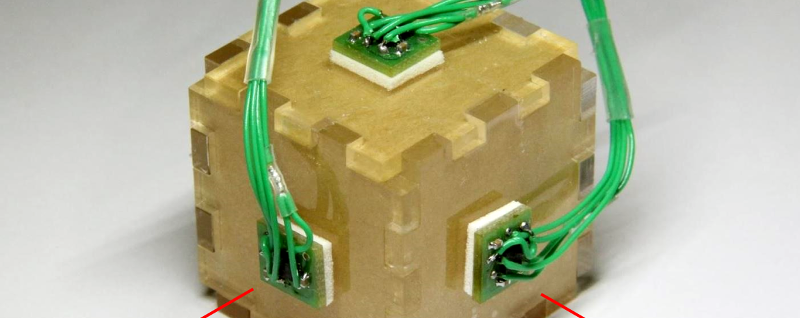
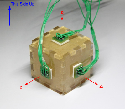
In both methods, I’m using the same sensor setup to check that each circuit behaves correctly. I happened to have a bunch of extra BMA180s on the bench, so I rolled out an example based on these chips. Back in the day, the BMA180 was a pretty common three-axis digital accelerometer. It has an I²C interface with two optional addresses. For the purpose of this example, I’m fixing them all with the same address. I’ve mounted three of these guys on mutually perpendicular axes of my acrylic “test cube,” and I’m reading each chip’s Z-axis. In this configuration I can easily pick out the gravity vector from the corresponding sensor as the data goes flying by my serial port window. If I can uniquely address each sensor and read the data, I’ve got a working circuit.
Method 1: Splicing Clocks into Chip-Selects
This method tips its hat towards SPI in that it behaves in an oddly similar fashion. If you’re feeling rusty on SPI, here’s a quick recap.
A Quick SPI Refreshment:
SPI, like I²C, is another protocol that shares both its clock and data lines with multiple slave devices. The difference, though, lies in the addressing scheme to talk to these devices that share the same bus. With SPI, while clock and data lines are shared, devices are addressed with separate chip-select (CS) lines.
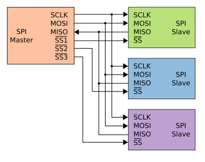
The master microcontroller dedicates a unique output pin to each device (~SS1, ~SS2, and ~SS3 in this illustration). When the master micro’ wants to talk to a device, it asserts that device’s chip-select input pin by pulling it to logic LOW, and the conversation begins over the data bus. With the chip select LOW, the corresponding slave listens to the data on the bus. Meanwhile, all other devices ignore the conversation between the master and it’s chosen slave by keeping their bus pins in a high impedance state.
Giving I²C Its Own Chip-Selects:
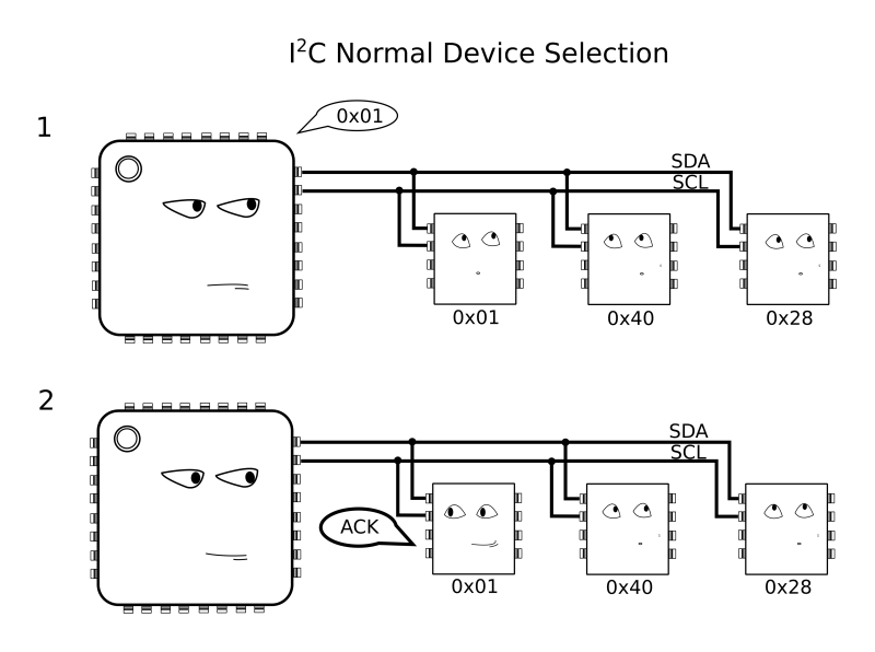
With I²C, Clock (SCL) and Data (SDA) lines are still shared between all I2C slave devices, but the addressing scheme happens by sending a message heard by all devices on the bus. To single out one device on the shared bus, the master first passes down the address of the slave device it wants to talk to, after which that slave replies with an ACKnowledge, and all other slaves ignore the data that follows until both data transmission is complete and the bus is “released.”
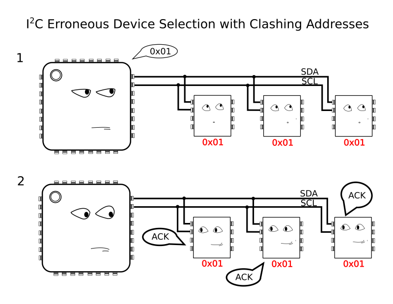
Because we have the problem of multiple devices with shared addresses, in theory, all of these devices would reply when the master passes down their shared address, and there’s no way for the master to single out a single device. In reality, this behavior is undefined on the I²C protocol.
Yikes! Anything goes when we wander away from defined behavior, so we try to avoid these things in practice.
The solution?
According to the I²C spec, It just so happens that an I²C slave device will ignore changes on the data line (SDA) provided that the clock line (SCL) is held high. In this method, I’ll “split” the SCL line into multiple SCL lines such that each shared I²C device gets its own SCL. By selectively rerouting the clock to each I²C device one-at-a-time, I’ve essentially turned the SCL line into a “chip select.”
To chop up that clock line, I’ll need a demultiplexer. A demultiplexer (or decoder) takes a logical input and reroutes it to one of several outputs based on the binary select lines.
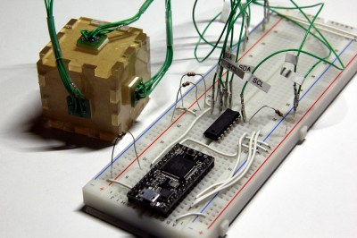 I’ve dropped in the 74AC11138 eight-way demultiplexer for this task. It’s fast, capable of switching at megahertz rates, and its outputs default to logic HIGH. That second note is handy since idle SCL lines also default to logic HIGH.
The setup is shown in a simplified schematic above. In it, I’m using a Teensy 3.0 posing as the I²C bus master. To the right of the Teensy is the collection of identical chips, BMA180 accelerometers in this case. In the middle is the 74AC11138 eight-way demultiplexer.
Cons of this Method:
There’s a minor drawback with this technique, though, in that it doesn’t support I²C’s clock-stretching feature. Taking a step back, this method assumes that the SCL line is inherently unidirectional, controlled by only the I²C bus master. In other words, we’re making the assumption that data on the SCL line is only sent from master to slave and never the other way around. If your I²C slave devices implement clock-stretching, however, this assumption breaks down.
What is Clock Stretching?
Clock stretching is a method defined by the I²C protocol where the chip needs to “buy itself more time” and holds the SCL line low, hence, signalling to the master that it’s not ready for the upcoming data. In this scenario, the slave actively controls the SCL line, and it happens to be the only case where data moves up the SCL line from slave to master. In a setup with our demultiplexer between the master and our set of identical slaves, these slaves won’t be able to send back the clock-stretching signal to the master to indicate that they aren’t ready for data, if they happen to implement clock stretching. That said, clock stretching is a pretty rare feature among I²C-compatible devices, so this method is likely to work among a number of chips out now.
More Next Week
That’s all for Method 1. Thanks for tuning in, and check back next week for a slightly-more-professional method of tackling this same problem.



You could use a bi-demux and clock stretching would work.
Only when you just happen to be listening to the particular device that is doing it.
I2C mux + IRQ lines into another I2C mux for interrupt-handling.
Also @PinheadBE : MAX7219 ist indeed not an I2C device!
When you aren’t listening to it, it’s not getting clocked at all, so something is pretty wrong if it’s trying to stretch the clock.
Exactly. The slave only talks on the bus in response to the master, so the master will keep the slave selected until it’s done listening to it. (Why would you want to let a device that you’re not listening to stretch the clocks anyway?)
Why do you talk about MAX7219 on a I2C bus? AFAIK, those are not I2C devices….
It’s SPI… probably a mistake. But it occurs to me — if you’re using a bunch of chip selects / mux / demuxers anyway… you could conceivably connect them to the same bus (in hardware), and switch back and forth between using the clock/data pins for the SPI and I2C protocols interchangeably (depending on which device you had selected and were talking to at any given point).
Seems like it would be simpler to just dedicate another couple of pins though…
You’re absolutely right! I must’ve searched for the wrong datasheet at a later time without thinking. I’ve replaced it with their I2C variant. That said, since there are four optional addresses selectable in hardware, this is still a bit of a canned example. My personal favorite replacement example is probably driving a number of ST’s VL6180X proximity sensors. Each of those has one fixed I2C address, and I can imagine some systems that would want multiple proximity sensors.
Wow, those have got to be some of the cutest I2C pictures I’ve ever seen.
Heh, my thoughts exactly.
The Micro-controller is too serious and grumpy. Maybe if he would just lighten up a bit then all would work out.
He has a lot of work to do.
https://www.sparkfun.com/products/9056
It worked pretty well. I hope the next method presented is something better
Now for the dirty way: instead of the demux, you could wire a resistor in series with the clock line separately for every device, and pull the actual device pin (so, the other side of the resistor) up with another I/O pin. This makes the “chip select” output pin of the microcontroller dominant, such that it can always drive the clock line of the device high or low. Only when this extra pin is switched to high-impedance mode (input mode), does the actual clock signal come through.
The value of the resistors is a bit of a compromise; too high and the clock signal will become shifted and slopes will be bad at high speeds, too low and the actual clock output of the microcontroller could be too heavily loaded. This shouldn’t be a huge problem unless you want to connect a very large number of devices and need a high data rate.
Nice!
Nearly as nice as the table “I2C multiplexer products” from http://www.ti.com/lsds/ti/interface/i2c-multiplexer-switch-products.page .
literally, 40s google research :)
I do love your article, though, for it’s nice explanation of CS and the illustrationary character of it!
You can alternatively mux the data line if you have a bi-dir mux. If you mux both, things get interesting. Lets say you have 2 2 way muxes and 4 devices. To talk to any one device, you mux both the clock and the data to that device. One of the other 4 devices will get clock, but no data, another data but no clock, and the final, neither clock nor data. This really starts to take off when you have say, 64 devices. You can manage it with 2 8 way muxes.
In the paragraph on SPI, “Meanwhile, all other devices ignore the conversation between the master and it’s chosen slave by keeping their bus pins in a high impedance state.” — Is it really “high impedance” and not “logic high”? (The two are very different. — Not sure about SPI, but usually chip selects are just logic high, and not high impedance. High impedance usually results in undefined / random behavior from leaving the gate floating…)
By “their bus pins” it’s talking about the MISO bus pins, not the chip select lines.
All data lines are on the same bus, so if you put idle ones in logic high you’re messing up data line and active device can not talk with master. If you put them in hi-Z state then it’s like they do not exist, so master and slave can talk normaly.
love the i2c selection pictures! what are the license on those?
Many Thanks David Anders! The originals are up on Github with a CC-A license:
https://github.com/Poofjunior/i2c_demultiplexing_demo/tree/master/pics
I’ve succesfully used this board in the past for circumventing the problem of multiple identical devices on one I2C bus: http://www.bitwizard.nl/shop/expansion-boards/i2c-splitter-PCA9548A
It’s just a small breakout board, but it saves a lot of hassle.
A way to make this trick work while allowing SCL to be bidirectional could be the trusty old 1-of-8 analog switch (74HC(T))4051, the only iffy thing I see is the Ron, which is in the 50-100 ohm ballpark and the various capacitances of that device.
I think there is another problem using something like a 74AC11138. Not only clock-stretching won’t work, it will result in a short-circuit because the slave will (try to) pull down a line that is actively driven high (whereas it normally only has a pullup resistor).
+This. I wonder if there’s an open-drain device suitable for this (or maybe a device to convert multiple push-pull signals to open-drain, something looking like ULN2803)
Maybe just a diode in series with the output (cathode directed to the chip) so the 1138 can just pull current but not push it? The problem are the 0,7V when the output is low.
Oh and of course a pullup behind the diode…
>The problem are the 0,7V when the output is low.
Looked it up, max. input voltage for low for the BNO055 is 0.25 or 0.3V depending on supply –> forget the diode thing, won’t work. :-(
Next week?! This is the era of Netflix full season dumps how will I manage?
watch something on netflix then?
There are also special ICs for this, typically controlled over I2C. For example: http://www.nxp.com/documents/data_sheet/PCA9547.pdf
PCA9547 is good choice as you said.
I2C multiplexers really are quite versatile and scalable.
I wrote a post a while ago to see just how many single-address devices you can *fit* on a bus:
http://mindbleach.com/words/i2c-and-device-limits/
There are added advantages to use I2C mux instead of wasting your time kludging a “solution”.
– it physically segmenting the bus into smaller segment. So you’ll have less capacitance on the bus. Capacitance is one big limitation on how fast and how many devices you can fit on the bus.
– In fault tolerant system e.g. a rack, you can isolate a fault on a card to card basis so that it doesn’t hang the I2C bus.
– these chips offers level translation, 5V tolerant. Need I say more?
Sorry for my bad english but what does “you’re best bet” mean ?
It should be “your best bet”. As in your best chance. The best thing to choose out of several alternatives.
If those alternatives were race horses, you’d be choosing your best bet.
Just a remark: “A demultiplexer (or decoder)” is kind of wrong. The demultiplexer and the decoder are 2 different digital circuits. The demultiplexer contains a decoder to select the correct output OR gate.
Grammar Nazi here: “you’re best bet” -> “Your best bet”
Sorry to burst your bubble, but there is a MUCH easier way of doing this, assuming no device has address 0x7F on the I2C bus (which I believe is explicitly disallowed): bit-bang the SDA/SCL, and have multiple SDA pins. Then if you leave SDA high on the buses that you’re not talking, they’ll see a message going to 0x7F, and no one ACKs on those buses. This is fewer pins (4 in the case shown, rather than 5), and has the added advantage that if you’re actually wanting to read multiple of the devices in a burst, you can send the same address/offset out to each bus and get all of the responses back simultaneously ;)
Yeah. Multiple SCL lines (1 to each device) with one SDA line (connected to all devices) will work too.
there are dedicated i2c multiplexers that, themselves, are i2c addressable. they can even route interrupt pins.
PCA95xx series
I have included an Excel file that is interactive with these “shortcuts” to show you how they will look when sent to the cube. The left table is a decoding of the axis value to LED, the middle table is where you put in your values to try it out, and the right tables are the output.