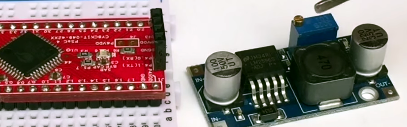
[Hugatry] wanted to replace the adjustment pot on an LM2596 buck converter with a microprocessor-controlled voltage. The regulator IC uses a divider to generate a 1.25V reference from the output. The pot is part of a divider circuit that sets the output voltage. For example, if the divider is 10:1, the controller will keep the output at 1.25V and, therefore, the output voltage will be 12.5V.
[Hugatry’s] strategy was to use a filtered PWM signal from a microcontroller to offset the 1.25V signal. By adding a small voltage to the control point, the output voltage would not need to rise as high as before to maintain the 1.25V reference. For example, adding 0.25V to the reference input would only require 1V, which corresponds to a 10V output.
The video has a nice view of a scope showing the relationship between the PWM duty cycle and the output voltage. Although he didn’t mention it, it struck us that since PWM is proportional to the supply voltage, the voltage on the microcontroller and PWM output stage probably needs to be fixed. That implies you couldn’t use the buck converter to directly power the microcontroller itself. Then again, what kind of microcontroller needs to adjust its own power supply?
If you need a refresher on how DC to DC converters work, we’ve got you covered. Or, perhaps you’d rather measure PWM in the strangest way imaginable.


One small note about these buck converters you can get on ebay for $1-2: The buck chip is actually a counterfeit LM2596 – and that’s why they can sell them on a pcb, with filter caps, inductor and diode at a lower price that you can buy just a bare, legit LM2596 for. You can verify it by measuring it’s switching frequency. A real LM2596 will be switching at about ~150kHz. The fake chips switch at about 50kHz. It’s not a deal breaker for most uses – if you’re not pushing it – and know it’s limits. But the 10 turn pot they supply on the board is the worst pot I’ve ever seen. You breath on it, and it will change the voltage – it’s that bad.
Thanks for that information! I just checked one and it sure does switch at about 50kHz. It’s good to know this kind of real differences between genuine and fake parts.
At first I thought of replacing the counterfeit chips with real ones.
I would expect the efficiency to increase (inductors are probably optimized for 150kHz, suffering by saturation at 50kHz, especially at higher currents), but it is likely that the other components are of that bad quality that complete rework would be needed anyway.
You might find this of interest: https://www.youtube.com/watch?v=JLwJb4MVbls
He’s looking at the high voltage version, where the fakes have a relabeled chip, plus bonus relabeled capacitors.
Problem is both the real (or at least to spec) & fake versions came from eBay.
I seen that video a while back, It’s crazy to sell components with specs above what they can do. There are so many fakes out there these days, That unless you buy direct you probably have a fake (atleast if you buy on ebay).
A lot of Chinese distributors do that these days. It helps them save money and sell more product.
If you need to know if a part is real or not, it is best to buy from a reputable distributor like Digi-Key
There is no such thing as an LM2596HV. To spec or not, they are all fakes.
Huh, there you go, so it’s a fake chip relabeled as a non-existent part.
The ‘real’ one was probably the 1A variant (LM2575HV), they can handle 60V. The bloke in the video confirmed the 60V rating, but I don’t think he checked current.
That’s not the only problem. These counterfeits will advertise 3A output current. A quick look at the datasheet shows that even if they were legitimate LM2596s they still fall far short due to component selection, especially cheaping out on capacitors where the component selection falls well short on capacitance, and even further short on voltage rating and ESR.
I have heaps of these fakes. I think they work great, but I wouldn’t put more than 15V or 1.5A through them without expecting them to catch fire.
I’ve tested some of these at high power levels. First one I tested ended up failing pretty quick as a dead short to ground. I thought the chip had died from overtemp (was pushing some decent temps and climbing rapidly). Turned out to be the piss-weak diode they’d used which was clearly not rated for more than 1A of switching current. Stuck a legit 3A diode in and it worked pretty well. Heat was still an issue though.
The ones I got off Aliexpress have SS34 SMD diodes on them which are supposed to be 3A/40V. I tested the forward voltage (low current using a multimeter) at 0.14V.
I tested a few of them with 12V in and 3.3-5V out, and they got up to a bit more than 2A before they’d start dropping. If I recall correctly the diode was getting pretty hot at that point.
I haven’t tested the switching frequency or the caps, but since I bought a pack of 10, I may get out the hot air gun and remove the caps to test them. They’re labeled 100 50V UT and 220 35V UT, both 8x11mm.
I always assume some chip is counterfeit if a module with other components is sold for less than I can buy the chip itself in quantities of 1000.
Here is also the trouble with ebay: feedback is per user, not per product. And the users are hungry for 5 stars, so they will do tricks to make sure they get them. That way you cannot really judge the quality of a module.
But many semiconductor companies have different (lower) pricing for Asia. Buy an ATmega328p-au from digi-key or mouser and they’ll cost ~175c/q1000. Pro mini boards with an ATmega328p-au go for as little as 145c on AliExpress, and I’m pretty sure you won’t find any chinese mfr that has cloned the m328. The closest thing to a clone is the LGT88A, but it is only compatible with the footprint, and the instruction set implementation is not cycle-accurate.
When ordering a cheap Chinese module, I never saw the sense of paying extra for what may or may not be a LM2596, if it’s probably going to be limited by cheap external components anyway.
I just get one based on the XL6009 instead. It’s cheaper, claims to switch at 400Khz (I haven’t verified), and being a Chinese IC in the first place it’s less likely it will be counterfeit. Therefore, even if it in some way sucks compared to a real LM2596, it will suck *consistently*, with no surprises on different boards.
Any known issues with those?
I’ve seen these too. Looks like they cloned a LM25xx and sped it up while they were at it, bringing it into the last 20 years. Whether the performance is actually there is something else, I’ll have to try sometime.
(I have no idea why LM2596 still exists, other than for replacement). There’s so many better, cheaper integrated buck chips out there. Since they have such low fet resistance and high speed, they make much less heat and a much (physically) smaller circuit too.
Ain’t nobody getting 3A out of those chinese boards in the OP, but even taking that into account (if you only need an amp), it’s hard to beat the price.
Can you give examples of buck converters that are better AND cheaper than the LM2596?
Pulled out the Rigol today to test the “LM2596” modules I bought a little over a year ago. As you suggested, I found the switching frequency to be 56kHz.
http://nerdralph.blogspot.ca/2015/08/dc-converter-modules-using-fake-lm2596.html
Combining this with a voltage divider and current shunt, a simple Arduino software can optimize the power output of a solar cell (normlay optimized power output is expensive and complicated for small systems). Well done!
Not the best idea. Once you get your hands on the voltage and current, you can use the PWM output to drive a MOS transistor and make a switching regulator on your own. For the same money and less parts you will get something more efficient and simpler.
That “micro-controller” board is looking very much like a Cypress PSoC 42xx ??
That is exactly what it is.
I just had a quick look around your site. I have just started with the same PSoC kit. I am having some trouble installing the software.
I noticed you bought a programmer on ebay.
Cypress has another cheap PSoC kit here –
http://www.cypress.com/documentation/development-kitsboards/cy8ckit-059-psoc-5lp-prototyping-kit?source=search&keywords=059
The above kit looks much the same but it has a full programmer / debugger (JTAG) instead UART. It also has more analog and some other features. You can snap off the USB to JTAG and use it to program the 42xx boards as well, without the boot loader.
That kit surely does look interesting. I’d be happy to pay that $10 for just the programmer/debugger part, if I was looking for one. Getting a debugger AND PSoC 5LP board for that is just awesome. :)
What comes to trouble installing the software, if you mean the PSoC Creator, I don’t remember having any problems with it myself (using 64bit versions of Win8 and Win8.1).
Good idea, but that op-amp will introduce some delay that will break the stability of the loop.
Also, there is some schematic in the video, why is there none in the article?
I found it odd that the Op-Amp was just being used as an impedance buffer. I would have used some 1% resistors and put the Op-Amp in the control/feedback loop then you would have precise and predictable control of the output without any calibration etc.
I’ve added (ASCII) schematic to my blog post, thanks for pointing that out.
No, the true feedback loop is not affected by the opamp as it is not part of it. Most likely it will be the other way round: The loop will be unstable without the opamp. The opamp acts as a buffer and decouples capacitor C_1 from the feedback loop.
You are right, i misunderstood what he did…. lack of schematic maybe.
@hugatry why the ASCII schematic? not the 80s anymore…plenty of free schematic software.
One trap that ‘designers’ fall into when employing Buck converters, is the failure to recognise that they generate spectacular quantities of EMI. Know their limitations BEFORE you get to EMC testing.
WoW man… dream come true, thanks you did this. I tried this for loooonnnggg… but my analog knowledge is limited. I actually tried it in LTspice simulator (obviously using LT’s switching regulator instead) but was never able to get stabilized output voltage. Now I know how to get it without simulation :) thanks to you.
Actually I never tried using op-amp in this way. I just did PWM and transistor+filter in feed back path. I guess that introduced lot of issues and hence output never stabilized. Second approach I tried was using op-amp as programmable gain amp (with negative gain to work as divider) and somehow control the gain using PWM, it did never work as well (Pleas stop laughing everyone.)
The cheap ones I got from eBay are running at ~150kHz, so they are not all fake, or these fakes run at higher frequencies too.
I’ve got a couple with current limit as well….50Khz, with apparent 150KHz parts…
Personally I like to keep the microcontroller out of the loop :) I was going to take one of those modules and use them with a digital pot, in the process I learned that the digital pots cant operate the pot above the logic voltage :( be aware that those modules have to have the load connected to the output ground terminal, as otherwise the current dosn’t go thru their sense resistor, which is the ONLY current limit to those boards. I been putting a lot of work into an alternate regulator.
I also have, somewhere, a little snippet of code that uses ADC feedback on filtered pwm output to ‘correct it’
https://hackaday.io/project/296-bench-power-supply
” filtered PWM signal from a microcontroller to offset the 1.25V signal”
A very bad idea. No matter how “filtered” the PWM signal is, you’re still likely to introduce undesirable interference into the switcher’s control loop, and either introduce instability in some input voltage / output current regimes, or cause the output of the switcher to become noisier than it already is.
A quieter approach, but one that requires more I/Os, is to configure several I/Os on the micro as open-drain outputs, and connect each to a resistor, in an array of resistors whose values are a binary R-2R-type array. The other ends of the resistors are connected together to the feedback input of the switcher. That way, all you’re doing is changing the bottom end of the feedback divider. Keep the leads between the micro and the resistors short.
Well, if it is really filtered, it would be pure DC with no ripple… So….
But likely if you measured the control loop of one of these switching chips, there would be way more noise on the line than you would have to worry about ripple from a properly filtered PWM signal interfering with it.
And oh yeah, I have done basically the same thing with LM317s and had no issues.
>and either introduce instability in some input voltage / output current regimes
Given how slow a digital PWM is when you crank up the PWM resolution, you are talking about order of magnitude of 100Hz range. it is unlikely to have any effects on a stability issues on a well design feedback loop. a 150kHz switch mode supply should be able to handle transients in the teens of kHz easily. The filtering will have a very large effect on the output ripple as the output will try to track the ripple.. The 1st order RC filter in the article is not going to cut it at all.
The other trick to getting a high res. DC output without a lot of filtering is to use an integrator and measure the output offset with a ADC. e.g. you drive ‘1’ to increase the output voltage *over time*, a ‘0’ to decrease and tristate to maintain it. You are building a power supply, so you don’t need a whole lot of high speed updates.
Backwood’s post is a better solution for another reason – at least the resulting system will have good load regulation. The PWM method will reduce the load regulation ability of the regulator, since you are artificially injecting or draining current from the voltage divider using a source that is not related to changes in load.
I had the same idea but to use the DAC on the 4200 instead of PWM. The DAC is only 8 bit but it only needs a single resistor so it removes the need for filtering. You may also be able dither the DAC to get another bit or two of resolution. Monitoring of the output with an ADC would also let you know if you are current limited.
I like this, but there’s a potential issue no one has mentioned. Let’s say you design a 0-12V adjustable power supply using this. You’ve written the MCU software so it initially sets the output voltage to zero, by immediately beginning to output 100% PWM, until told otherwise. You hook up a 5V max part, and turn on the power supply. No problem, right?
Wrong. The requested output voltage, by default, will be the highest voltage. Until that RC low-pass filter charges up, and as shown, it has a time constant of 10ms. Fortunately the regulator also has a soft-start time of some ms, but it’s a race between the two. Who wins? I don’t care to bet on that 5V component not blowing.
And if the MCU is on a separate power supply with a longer soft-start time than the supply feeding the regulator, the MCU fuse bits are set to provide a required oscillator PLL settling time, or you increase the RC time constant to reduce ripple, it gets worse.
Just something to be aware of. I failed to account for a similar issue in one of my aquarium lighting projects. When power is turned on, it was intended to gently increase light, to avoid startling fish. The effect was ruined by the initial strobe-like burst!
Yeah, I think he would have been better off using a digital pot to replace the manually adjusted one. Then you won’t need to worry about these issues.
I do see the appeal of avoiding a digital pot:
1) A digital pot is more expensive and less common than an op-amp. In some parts of the world you might be forced to order one from overseas.
2) Many digital pots have limited supply voltage. The ones I have are 5.5V max. In my example, I wouldn’t be able to run it off the >=12V rail feeding the regulator. I’d have to run it off the 3.3V/5V MCU rail, and depending on how that is derived, there may still be a power-up timing issue. What would be the behavior of the digital pot if it’s not yet powered?
3) A digital pot is inserted into the control loop. AFAIK it responds quickly enough that it normally doesn’t cause issues with loop stability, but if the loop is already on the border of instability, who knows.
The op-amp approach might still be made workable. Perhaps it’s as simple as using it in an inverting buffer configuration instead. I plan to look into this further but am pressed for time ATM.
The well tuned PCB design “matters the most” in case of DC-DC converters. Generally DC-DC converts are vulnerable towards parasitic inductance and capacitance due to its “switching mode” operations.
Although copying layout from EVM or reference boards is the easiest way but in most cases at system level boards, this shortcut doesn’t work.
Below are some issues occurs due to poor layout-
High ripples in output.
Unstable switching waveforms.
Audible noise from magnetic components.
Less accuracy for current and voltage limit circuitry.
Thermal stress.
Electromagnetic interference (EMI)
I have worked on basicat pcb layout level and tested around 10-15 pcbs and found some effective practices to neutralize all above effects at layout stage.
for more details follow
my blog-http://theelectronifide.blogspot.in/
or read full article on linkedinhttps://www.linkedin.com/pulse/best-pcb-design-practices-spot-dc-dc-converter-bhaintwal-c-i-d-/