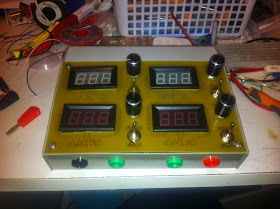
[Hugatry] wanted to replace the adjustment pot on an LM2596 buck converter with a microprocessor-controlled voltage. The regulator IC uses a divider to generate a 1.25V reference from the output. The pot is part of a divider circuit that sets the output voltage. For example, if the divider is 10:1, the controller will keep the output at 1.25V and, therefore, the output voltage will be 12.5V.
[Hugatry’s] strategy was to use a filtered PWM signal from a microcontroller to offset the 1.25V signal. By adding a small voltage to the control point, the output voltage would not need to rise as high as before to maintain the 1.25V reference. For example, adding 0.25V to the reference input would only require 1V, which corresponds to a 10V output.
The video has a nice view of a scope showing the relationship between the PWM duty cycle and the output voltage. Although he didn’t mention it, it struck us that since PWM is proportional to the supply voltage, the voltage on the microcontroller and PWM output stage probably needs to be fixed. That implies you couldn’t use the buck converter to directly power the microcontroller itself. Then again, what kind of microcontroller needs to adjust its own power supply?
Continue reading “Microcontroller Adjustment Of A DC To DC Converter”


