PID control loops are everywhere, found in flight controllers for drones and the temperature control code for 3D printers. How do you teach PID control loops? [Tim] has a great demonstration for this, and it’s also a semifinalist for the Hackaday Prize.
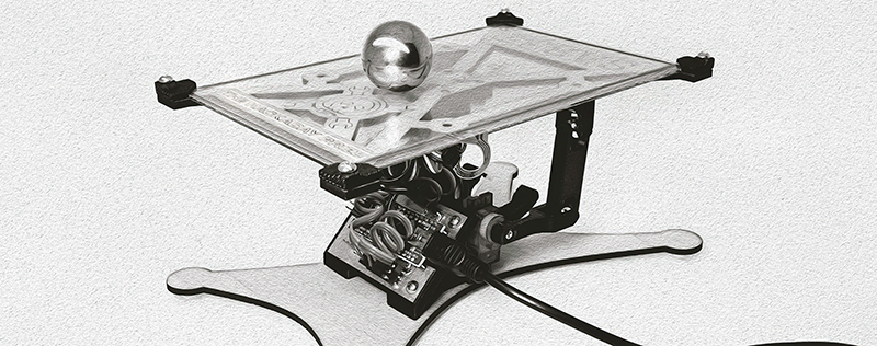
[Tim]’s Sab3t is an educational tool designed to illustrate how PID control loops work. It’s a robotic table on which a large ball bearing sits perfectly balanced. On this table is a resistive touch screen from a display providing feedback for the location of the ball bearing. By adjusting PID values, the ball bearing either sits stationary on the table or flails wildly around, depending on the values in the PID algorithm being used.
As a teaching tool, it’s great; with a python script displaying a log of the PID values and the position of the ball on the plate, anyone can easily visualize how oscillations happen, what a well-tuned control loop looks like, and have some fun moving the ball bearing around to different locations.


At first I thought this was going to be like an inverted pendulum, and those are NOT a good way to demonstrate PIDs since one of the gains is negative and I was going to complain about it.
But looking at this, it’s not like an inverted pendulum, so I learned something this morning.
Then looking at the code. (At least what I think is the code) I got confused again.
This looks like PID with feed forward gain, which is once again, NOT a good way to teach PID since the feed forwardness completely messes with the normal analytical tools you could use to tune a PID loop.
And then looking further into the code, I get confused. It looks like the authors are trying to average the estimation of the position of the ball, but they clear their accumulator every time through the loop, so I don’t there’s any averaging going on. I certainly could have misunderstood the code.
I also thing the Integral error calculation is completely wrong. It looks like (and once again, I may be misunderstanding something) the author sets the integral error to one half the position error and doesn’t actually integrate anything.
So, as a PID demonstration, this might be bette used as a fail of the week.
On a “That’s a really beautiful piece of work and I really want one” and “Oh hell, that’s a brilliant idea using a touch screen as a 2D ball sensor for a stability and feedback demonstration”
A+ on the ideas man. This is great in the mechanics of the project.
PID demonstration, not so great.
It could be improved by implementing a good PID (Plenty of PID tutorials in C that could be used) along with some knobs and P, I and D value displays so someone could play with it.
I was going to say that the integral term seemed to be misbehaving or badly tuned, since the ball wasn’t pushed back to the center (i.e. driving the integral error to 0), but only stopped the ball from moving.
Your comment explains why that’s happening
But if you are right it should not balance the ball right? But it does.
So how can you conviction overrule reality?
What I poorly phrased was that this is a traditional completely linear control system, not an inverted-pendulum style control system which has a negative proportional gain.
So, it’s not inverted. I could have been more clear.
Ah OK, thanks for clarifying, I never tried to do this so I’m not up on the various ways and terminology either so it was a bit confusing.
While on the subject of code.. I would add recommendation of putting the PID controller in a timer based interrupt. It’s very bad practice to put PID code in your main loop (even if you are compensating for the variations in dt by tracking loop time).
I would recommend putting* – Pardon my grammar, I commented before having coffee.
This is a great concept! My university control systems course had a small motor control board and different loads that you could apply to the board. The software that went along with it plotted motor position and speed, but it never gave you access to the guts of the control system itself.
That was a failed opportunity, as my course had you essentially taking screenshots of work that somebody else had done, but this project looks like it lets you get right under the hood and come up with your own gain values.
Could be kind of fun to come up with values to see who can make the strongest stable oscillations :)