[Henrik] is at it again. Another thoroughly detailed radar project has shown up on his blog. This time [Henrik] is making some significant improvements to his previous homemade radar with the addition of Synthetic Aperture Radar (SAR) to his previous Frequency Modulated Continuous Wave (FMCW) system.
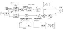
[Henrik’s] new design uses an NXP LPC4320 which uniquely combines an ARM Cortex-M4 MCU along with a Cortex-M0 co-processor. The HackRF also uses this micro as it has some specific features that can be taken advantage of here like the Serial GPIO (SGPIO) which can be tediously configured and high-speed USB all for ~$8 in single quantity. The mixed signal design is done in two boards, a 4 layer RF board and 2 layer digital board.
Like the gentleman he is, [Henrik] has included schematics, board files, and his modified source from the HackRF project in his github repo. There is simply too much information in his post to attempt to summarize here, if you need instant gratification check out the pictures after the break.
The write-up on his personal blog is impressive and worth look if you didn’t catch our coverage of his single board Linux computer, or his previous radar design.


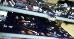
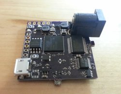
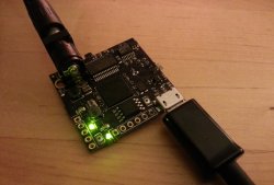
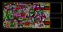


I have a serious hardon for this guy, in the most platonic and intellectually respectful way.
Let’s fight for his brain!
This is totally sweet, what is the approximate BOM cost?
Is it violating any laws?
As long as it stays in the ISM band (and the output power is within FCC limits), I do not see what laws it could be breaking.
“Total cost was about 200€. PCBs were 28€, components were about 120€, battery pack was 21€ from China and antennas were made from scrap metal.”
5GHz is not an ISM band. Not sure about Europe, but in US the band is shared with doppler weather radars used at airports (TWDR), and many other users. Long story short, wifi routers can be used on non-interference basis, and this is the reason why they employ dynamic spectrum and power control, and why some channels can not be used. More on the topic: https://wirednot.wordpress.com/2014/01/07/what-else-is-in-the-5-ghz-spectrum-hint-its-not-just-weather-radar/
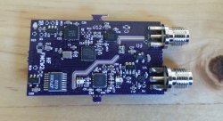
Both RF and digital board have 4 layers.
Yeah, just like any low density design that needs signal integrity with high frequency stuff going on in a loud RF environment.
Please take the effort of filing away the little break tabs at the edge of the board, guys.
For a second I was wondering why they went with a LPC4320 and not a LPC4370 (with a built in 80MSPS 12-bit ADC). 95% of the source code would be the exact same. I was thinking that there was no way that a LPC4320 ($8) and a MAX1426 ADC ($5) could possibly be cheaper than the cost of a LPC4370 ($9). But then I realised the reason, not having to deal with a TFBGA-100 (or TFBGA-256), you can even hand solder the LQFP-144. And if you used the 4370 you would probably need s 6 layer PCB as well, the $4 saved would end up costing more than that on the PCB.
They used a BGA for the LPC4320, now I am confused!
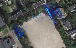
Is there any tutorial on how to read a graph (or a visual) generated by a SAR? I’m kinda lost how to interpret that image on the banner of this article.
That is the view across the field walking “up” and looking to the right. There is a bike rack up between 0 and 10 near the left. The repeating pattern across the top is the poles of a fence for the playing field and the vertical lines on the right are the walls of buildings. The RADAR basically looks through the trees. Check the blog.
This is really cool. Amazing features of SAR include the wider the beam the better the results (basically more pings on an object means more information) and it exactly counteracts the effect of distance so that as long as you can receive an echo, resolution is independent of range. I have wanted to do this with SONAR for decades and never found a transducer I liked that would do a chirp, or noise. Anyone know an inexpensive way to get a chirp in water?