The new Raspberry Pi Zero is generating a lot of discussion, especially along the lines of “why didn’t they include…?” One specific complaint has been that audio is only available through the HDMI port. That’s not entirely true as pointed out by Lady Ada over at Adafruit.
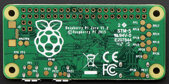
Something to remember about the entire Pi family is the pins on the Broadcom processors are multipurpose. Does it increase the confusion or the capabilities? Take your pick. But the key benefit is that different pins can handle the same purpose. For audio the Greater Than Zero Pis (GTZPi) use PWM0_OUT and PWM1_OUT on the processor’s GPIO pins 40 and 45. On the GRZPis these feed a diode, resistor and capacitor network that ends at the audio output jack. They don’t appear on the GPIO connector so cannot be used on the Zero.
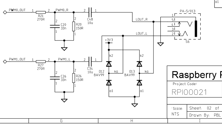
The multi-pin, multi-purpose capability of the Broadcom processor allows you to switch PWM0_OUT to GPIO 18 and PWM1_OUT to GPIO 13 or 19. Add the network from the Adafruit note, or check this schematic from the Raspberry Pi site – look at the lower right on the second page.
While you’re checking out the audio hack at Adafruit, read through the entirety of Introducing the Raspberry Pi Zero. Lady Ada provides a great description of the Zero and what is needed to start using it.
If you’re looking for Zero hacking ideas you might check the comments in our announcement about the Zero or article on the first hack we received. There is a lot of grist for the hacking mill in them.


Love the way Lady Ada documented that hack. Sets the standard for us all :)
There is also an ethernet hack I published this week…
http://raspi.tv/2015/ethernet-on-pi-zero-how-to-put-an-ethernet-port-on-your-pi
It’s only 4 MBaud, but better than nothing.
Anyone know how to get RCA out?
Put RCA connectors on the circuit shown above from the Pi foundation. The signals there are line level, not ready to drive headphones.
Do you mean composite video output?
It’s the two pins labeled TV below the gpio header. Between them there are another two pins that when shorted reset the raspberry pi
But that’s not RCA… That is composite Video.
RCA takes a lot of math and programming to get a good output. More information about it is here ….
http://rootcause.com/what-is-rca
pizero got dedicated rca out – so adding audio out was to be expected – – i guess best would be to conjure this into 3,5jack out
What? You are confusing root cause analysis with a standardized electrical connector invented before I was born (and I’m pretty old).
RCA in this case is not a video or audio format, it’s a connector. RCA connectors are used for things like- line level audio (1Vpp), composite video, and component video.
Or- you are bored and joking. Or- you are drunk and typing.
An RCA video output cable carries composite video and 2 channel stereo. If you Google search RCA you’ll get hits for the RCA brand and pictures of the cable I described on the first page. I Googled RCA and went 10 pages deep and found no mention of root cause analysis. I think you are just being an ass, who went 100 pages deep on google to find a “bacronym” for RCA.
rca is just the connector for video, audio, digital audio, rf video audio combo (nes, c64) and may other signals. composite is the video standard usually carried over an rca plug of the yellow color. there is no audio unless there are one or more additional audio plugs.
by chance are you thinking of composite video and line level audio on a trs connector, like the pi2?
yes … but rca type conection of video requires 3 channels – LEFT-RIGHT-VIDEO … and if you look at the RCA output on the raspberry pi zero – it is TWO HOLES – – -> VIDEO CHANNEL ….. that’s why separate output for audio is required for what you recall in general as RCA connection ( which is actually THREE cables – or the SCART TV variant ) – – – — — > after all , that’s why i think the both hacks desrve merge for the new 3.5 jack with video channel – so a simple cable like this ….. … can be used
http://img.dxcdn.com/productimages/sku_231541_1.jpg
The easiest way would be this one: https://shop.pimoroni.com/products/phat-dac , it’s got a place for RCA connectors that you can also get from Pimoroni.
RCA is a connector type, composite video is luminance and chrominace mixed together with the horiz and vertical sync … The rca connector came from : Radio Corporation of America known as RCA …
here’s a wiki : https://en.wikipedia.org/wiki/RCA_connector
I’m guessing the diodes are to short any voltages outside the range of 0 to the 3.3 volt of the pi.
But how likely is that to happen? And for what reasons?
ESD?
Voltages on the receiving end? (Audio in Jack)
There are two reasons-
The diodes are used for reason you mentioned, the help protect against someone applying a voltage that is outside of the range you mentioned, or a small electrostatic discharge.
The diodes will also clamp the peak value of a sine wave that you are trying to produce from the PWM lines to a maximum value of two times the forward voltage drop of the diode. In this case the forward voltage drop will range from 0.715V to 1.25V depending on current flow through the diode. So in this case the center of the sine wave will sit at 1.65V above ground, and be limited to a peak to peak value of ~1.43V. This is often done to help prevent damage to audio equipment that someone may try to use to amplify the signal. C34 and C48 are critical for DC blocking and without them the DC offset will cause one diode in each channel to conduct continuously.
Thanks. I read and thought about your explanation. I can’t figure out how “the diodes well clamp the peak value of a sine wave that you are trying to produce from the PWM to a max of two times the forward voltage” .
Did you mean “peak to peak”?
If so, does this mean 1.43 v is the max swing (p2p), that some spec specifies for audio in?
(I was thinking a peak2peak of ~3v3 would be okay, but clearly there is a limit and maybe 3v3, while low in my mind, is too high.)
Thanks for your help!
Yes, peak to peak. The positive (relative to the 1.65V midpoint value) part of the sine wave will cause one diode to conduct if it exceeds the forward voltage of that diode, so you end up with the positive part of the sine wave having a maximum value of 1.65V + 0.715V (the forward voltage drop of the diode) = 2.365V.
The negative (relative to the 1.65V value) part of the sine wave will cause one diode to conduct if it exceeds the forward voltage of that diode, so you end up with the negative part of the sine wave having a maximum value of 1.65V – 0.715V (the forward voltage drop of the diode) = 0.935V.
So the maximum peak to peak value of the signal is 1.43V. The exact value will vary if different diodes are used, and it will depend on the amount of current flowing through the diodes.
The line level audio inputs on most home stereo equipment have a maximum input amplitude of 1V peak to peak, but can withstand 1.5V as an absolute maximum, even though this will cause distortion in the amplifier due to clipping the peaks off the sine waves.
Hmm… I asked the above question thinking that the diodes were reverse in polarity to the way they were in the diagram. But it seems like your explanation also thought they were reversed.
So a sort of follow up/replacement question is this (ie please answer my previous question if it makes sense):
How can the diodes short any *signal* out side of the 1.43 peak 2 peak range? That signal, centered at the middle of 3v3, would never be below 0 or above 3v3. And if within this range, the diodes would never conduct because they are reversed biased.
Thanks!
The signal does not need to go above 3.3V or below 0V. The diodes will not normally conduct unless the signal exceeds the forward voltage of the diode, so as long as your signal is below that ~1.43V peak to peak level, you will get a nice sine wave out of this circuit. If you go over the ~1.43V peak to peak, the tops of the sine waves start to get clipped off and the audio will sound distorted.
Hmm…
The upper diode’s negative lead is connected to 3v3. So that diode’s positive lead (connected to the signal), must go to 3v3 plus ~0.7 volts to conduct. But how can the signal ever go above 3v3?
Oh, this whole time I’ve been assuming the pwm0’s max is 3v3. Maybe it goes higher….I’ll look at the spec.
Thanks for explaining!
So, – The cathode of the upper diode is connected to 3.3V, but its anode is connected to the 1.65V virtual ground (as Dave said below) so the anode only needs to get to 2.365V before it starts to conduct. The voltages are all relative to this virtual ground that is constantly changing with the sine wave, so it is a little hard to visualize.
But, from the other direction, if you were to apply say 5V to that connection by accident, or if there is an electrostatic discharge, then a positive voltage of 3.3V + ~0.7V will turn on the upper diode as you said. Or if you were to apply a negative voltage of more than ~0.7V the lower diode will conduct.
The PWM outputs can produce 3.3V if the duty cycle is set to 100%, but the resistors R20 and R21 end up dividing the voltage to around 1.1V peak to peak. R21 is also part of a low pass filter with C20.
“The cathode of the upper diode is connected to 3.3V, but its anode is connected to the 1.65V virtual ground (as Dave said below) so the anode only needs to get to 2.365V before it starts to conduct.
”
But… but …but, there is only one real measurable voltage at the upper diode’s anode with respect to real ground (real ground= the anode of the bottom diode).
So 3.3v at the upper diode’s cathode and 2.365 v on that diode’s anode. It is reverse biased. How can that conduct?
I thought I knew how diodes worked…Thanks for being so patient!
I can see how it would conduct if the 1.65 is added to the 2.365 (=4.015), because then the potential of 4.014v is dropped across the diode in the proper direction for flow. And 4.015 – 3.3 equals the forward bias drop off the diode (.715v)
The reverse bias makes no difference in this case because they don’t conduct (except for leakage) unless the forward voltage is exceeded.
The sine wave is changing the value of the virtual ground created by the two diodes in series. It would normally be 1.65V if no sine wave is there, but the sine wave is increasing or decreasing this value as the sine wave goes by.
This feature is not unique to Broadcom or anything Raspberry Pi. Almost all modern ARM SOC’s have multi purpose reconfigurable pins. It’s sorta like having the flexibility of an FPGA without having the pain of synthesizing the IP (at least as far as pin assignments go). Modern Allwinner, Rockchip, and many others all have this capability. Your Orange Pi’s, Bananna Pi’s, Cherry Pi’s, Shepards Pi’s and what have you all have this. Just grab the datasheet and discover for yourself.
Not even new to ARM socs. Old as the hills. Its even on Atmel parts!
Aha why is there not a Shepards Pi?! Or perhaps a Cottage Pi, I think Shepards are out of season.
is this available on all version of pi?
It’s available on all Pi’s, but on Pi B and A, you only have mono out.
On pi B+, A+, 2B, Zero, cm you have stereo output
Laurens
Take away the features and make it bare bone, critics will complain, hackers will get creative.
I’d like to think that the complaining and creativity are not mutually exclusive in hackers
Well.. More likely, while people who like to call themselves hackers, or “real engineers” were complaining, the people who actually are hackers and engineers got busy.
And got shit done.
So.. In the past few days..
OMG.. no networking.
Wifi dongle skinned and soldered in..parallel to the USB
Oh noes.. there is only one USB.. doooooooomm
Hub skinned, integrated and tested.
Now.. But but, how can I get sound out.. This is useless.
Sound already there, just switch from HDMi sound to GPIO..
Good thing the whiny people got their click bait in early. Because now every whiny article can have a dozen links to solutions
I seriously don’t get this stuff. Buy a Raspi A+,B+ if you want audio FFS.
Isn’t this what the I2S pins are for!? If you’re gonna go put components on an external PCB, then put an I2S DAC on there and get decent sound, not PWM crap.
would these be the correct components to recreate the filters?
http://www.ebay.com/itm/100-x-Resistors-270-Ohm-1-4W-5-Carbon-Film-USA-Seller-Free-Shipping-/231558081603
http://www.ebay.com/itm/100-x-Resistors-150-Ohm-1-4W-5-Carbon-Film-USA-SELLER-Free-Shipping-/221946406235
http://www.ebay.com/itm/50-pcs-033uf-0-033uf-33nf-50v-disc-ceramic-capacitors-red-/380464005364
http://www.ebay.com/itm/10uf-10mfd-450V-Electrolytic-Capacitor-6-pieces-RADIAL-leads-/281574595666