Nerd Ralph loves cheap and dirty hacks, and for that we applaud him. His latest endeavor is a LiFePO4 battery charger that he made out of parts he had on hand for under $0.50 US. (Although we think he really made it for the fun of making it.)
The circuit is centered around a TL431 programmable shunt regulator, which is an awesome and underrated chip in its own right. If you don’t know the TL431 (aka LM431), you owe it to yourself to fetch the datasheet and pick up a couple with your next electronics part order. In fact, it’s such a great chip, we can’t resist telling you about it for a minute.
TL431


Despite its misleading electrical symbol, think of the TL431 as being a voltage-activated switching transistor. When the voltage on the reference pin is lower than 2.5V, the transistor doesn’t conduct. When the voltage on the reference pin is higher than 2.5V, the transistor acts as a closed switch, sinking around 100 mA of current to ground.
If you tie the reference pin to the cathode, the TL431 does behave like a zener diode that has a breakdown voltage of 2.5 V, but that’s selling it short. The TL431 is a full-fledged IC with a precision voltage level reference, a comparator, and the active transistor all bundled up inside. The ability to put different voltages on the reference pin and the cathode make it interesting.
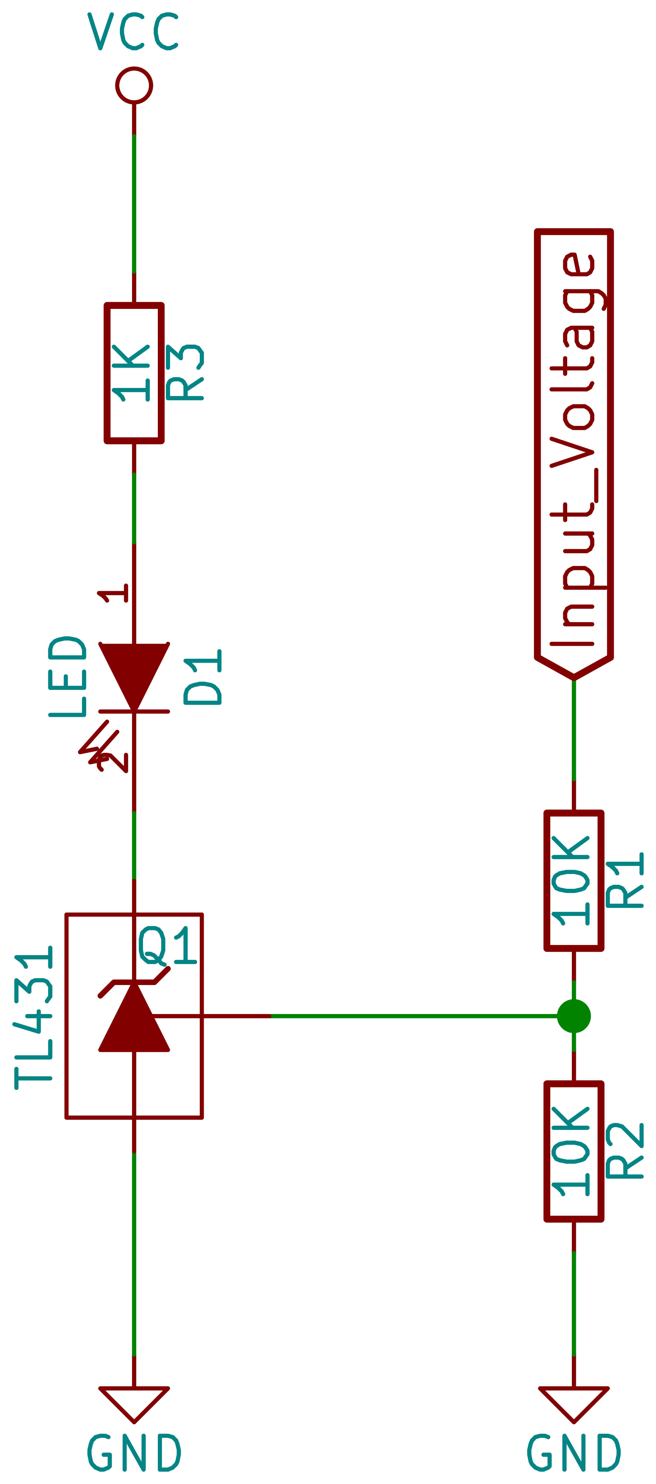 In the simplest circuit, you could drive an LED with a TL431. Connect an LED and a current-limiting resistor up to the cathode and ground the anode of the TL431. Then, when the voltage on the reference is higher than 2.5V, the LED will light up brightly. 2.5V isn’t interesting to you? You can add a voltage divider to increase the threshold to any value above 2.5 V that you’d like. Shown here is an LED that only lights up when the input is 5V or greater. You can use this idea anywhere you need a voltage activated switch, for instance as a battery’s low-voltage monitor.
Battery Chargers and Feedback
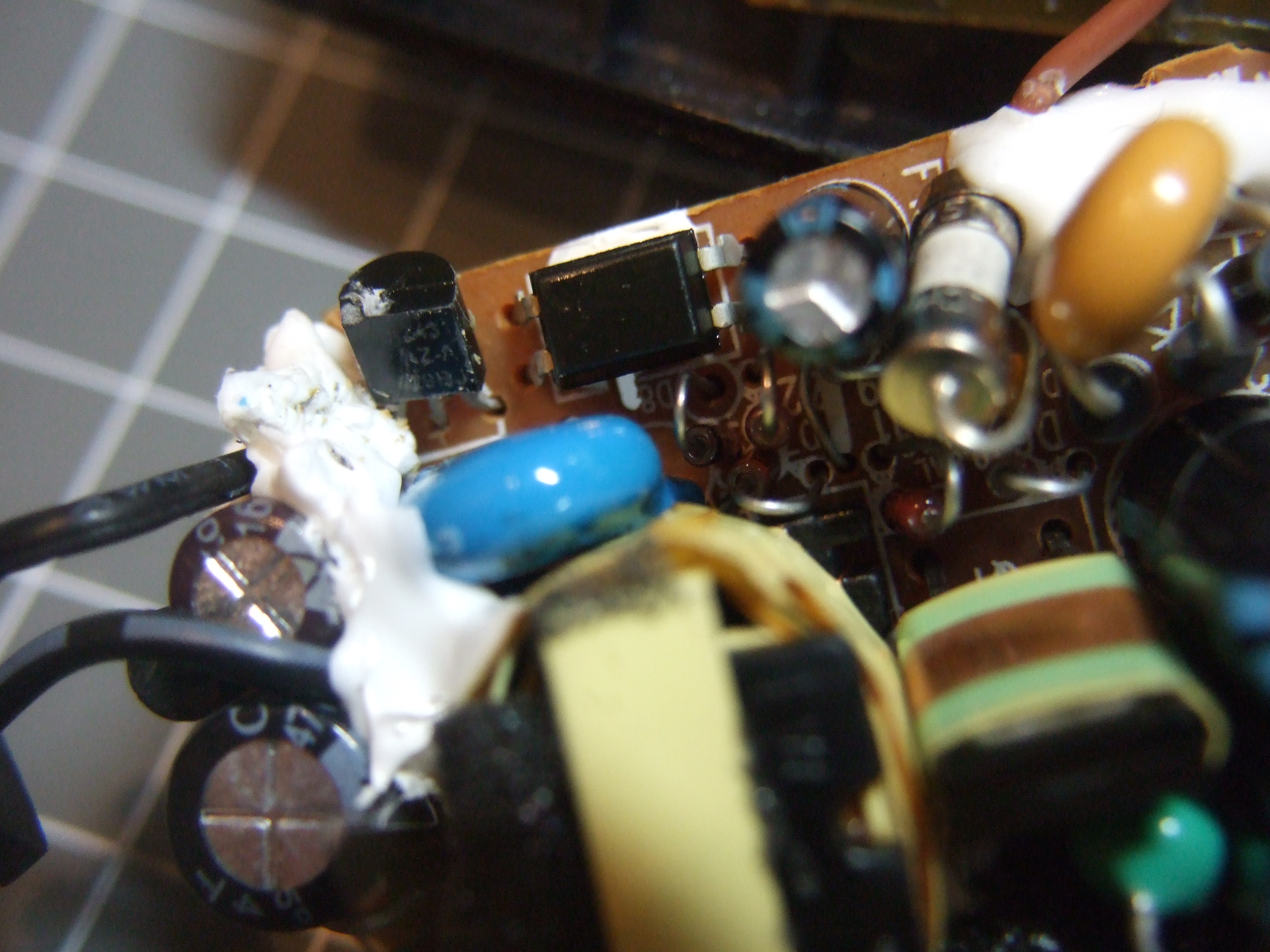
The TL431 is fine as a switch, but it thrives on feedback. To make a voltage regulator from the LED circuit shown here, all you need to do is add a transistor in place of the LED; have the TL431 turn the transistor on when the voltage drops below a target voltage and off when the voltage rises above. Indeed, this cheap and cheerful voltage regulator application is where almost all of the TL431s end up — providing voltage regulation in switching power supplies. You’ve probably got a few in your computer’s power supply right now, as a matter of fact.
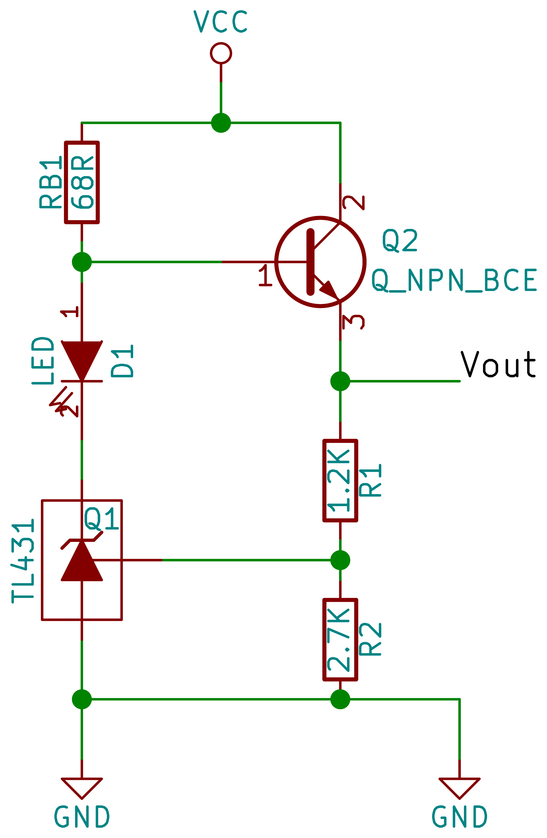 So let’s go back to Nerd Ralph and his battery charger. Ralph’s simple battery charger is essentially this simple voltage regulator circuit. He chose the voltage-setting resistors
 R1 and R2 to give him 2.5 V on the TL431 when the output sees 3.6 V, the voltage which a LiFePO4 battery is basically done charging.
To see the TL431 in action here, first imagine that it’s not conducting (off). Current flows from the power supply through RB1 and into the transistor, turning it on. The voltage at Vout increases, the battery charges, and the voltage in the middle of the voltage divider increases proportionately. When it reaches the 2.5 V threshold, the TL431 turns on and draws current, robbing the transistor of its base current and lighting the LED at the same time.
Because LiFePO4 batteries like to be charged with constant current nearly up to the end of their range, Ralph picked the transistor’s base resistor RB1 to limit the maximum current delivered to the batteries. He tested the output current into a half-charged battery to verify that he was in the right ballpark.
Now we’re not entirely sold on this being a constant current charger circuit. The basic circuit is a voltage regulator, after all. Relying on the transistor’s current gain to be constant over temperature or across different transistors is a bit sketchy — for instance the Art of Electronics warns you explicitly about the variability of the current gain value. But the LiFePO4 cells look like they’re pretty robust compared to their other lithium battery cousins, and the voltage profile only really varies from 3.4 V at 10% charge to 3.6V at 90% charge. Constant enough.
It’s also missing a bunch of things we like to have in other LiPO chargers, like battery temperature sensing and disconnect at charge completion. But again, the LiFePO4 cells are robust enough to overcharge that he’ll probably get away with it if he doesn’t leave the batteries in the charger for very long. It’s a hack, after all.
Kudos and Comments
So first, we’d like to thank Ralph for reminding us of a very useful part for minimalist electronics. The TL431’s datasheet is full of cool applications, and the combined functions of a voltage reference and comparator-driven transistor in a couple-cent piece of silicon make that work. If you need a voltage-triggered switch anywhere in your project, you now know where to look.
Ken Shirriff has written a very nice dissection of the TL431 that includes die images. And for a truly esoteric use of the TL431, here’s a crystal radio design that abuses the TL431 as an audio amplifier.
What do you think of Ralph’s charger design? Do you have any favorite tricks for the TL431? What piece of silicon would you rate as an unknown gem in the rough? Let us know in the comments and send in a tip for parts you’d like to see featured in the future.


Thanks for the simple useful hack!
There is an error in the schematic above. The anode of the LED should be tied to the base of the transistor, not tied to the +VCC rail. this schematic (as drawn) will over charge the battery.
I saw that too. Someone please correct this.
Not only that, if the device is a 100 mA current sink, it will destroy the LED.
The whole schematic is horribly wrong.
You guys are right. I added this in from Ralph’s description, and I was even worried about the LED, but I did it wrong regardless.
If you’re coming in late, and you see the LED pulling from the base of the transistor, all’s well.
There’s still the problem that 68 ohms might not be enough to protect the LED from overcurrent, depending on what the input voltage is and what the forward drop of the TL431 is.
Even in the fixed circuit, if the resistor and LED see 5 volts across, the LED will get about 40-50 mA through which is twice as much as regular indicator LEDs can handle, and the LED will still burn after a while.
The problem is that the same resistor is also responsible for moderating the charging current, so if you increase the R then your battery will charge too slowly, and to solve that issue you have to find a transistor with the exact right current gain, which is not practically possible.
So the circuit really is a hack – in the sense that it works in particular circumstances with particular components, but anyone trying to replicate it will likely fail.
The error is present in the original circuit as well:
“When Vout reaches 3.6V, the tl431 will shunt most of the 11mA from the transistor base, making the LED glow brightly.”
He’s assuming that there’s still just 0.7 Volts difference across the resistor when the TL431 switches, but this is not the case. The voltage becomes the full input voltage minus whatever voltage is lost in the LED and TL431. In this case, if the input is 5V then the resistor can see between 1.3…2.8 V depending on the TL431, which corresponds to 20…41 mA which is running the LED really bright – and hot – assuming it’s a regular plastic dipped indicator diode. 15 mA would normally be bright enough.
The most likely failure mode is open circuit, which means the circuit fails to cut the charging current and the diode will never light up to indicate a full battery.
The voltage across the tl431 will be > 1.8V (see discussion below started by [Louloulou]). The diode Vf is 2V, so we’re up to 3.8 now. Even if your USB supply is putting out the max 5.25V, the voltage across the 68 Ohm resistor is no more than 1.45V, giving a current of 21mA. Most cheap 3mm LEDs are rated for 25mA continuous current.
For example see the following Kingbright LED datasheet. With 2.2Vf, you’d get ~18mA peak current through it.
http://www.farnell.com/datasheets/67148.pdf
“The voltage across the tl431 will be > 1.8V”
That’s not given. I’m looking at a TI datasheet for the TL431 that has a graph saying the voltage can be <1.5 V with less than 50 mA of current.
“That’s not given. I’m looking at a TI datasheet for the TL431 that has a graph saying the voltage can be <1.5 V with less than 50 mA of current."
That's impossible (or it is an errata). The reference current will start to switch from the base-emitter junction to the base-cathode junction when the cathode voltage drops below 1.8V.
Also, looking at figure 2 (The inside the IC schematic) , It shows a diode from the (R)reference pin to the (K) cathode pin. If this were the case, the (K)cathode pin cannot ever get below about 1.7 volts, (because the internal diode from the (R)reference pin would go into conduction) Is this really the case? If the (R) reference pin is driven above 2.5 volts, and lets say the (K)cathode pin were pulled up to 15 v thorough a 10K resistor, what would the voltage of the (K)cathode pulled down to? Is it the .2 volts of a saturated BJT, or is it 1.7 volts as this internal schematic would indicate?
The internal circuit would need some minimal voltage to bias the shunt transistor, so that can rule out the 0.2V. Some datasheets shows a more detailed transistors version of the internal circuit. Datasheet have set a recommended operating voltage from Vref to 36V.
I would guess that it’ll be pulled down to around 2V give or take hundreds of millivolts.
So, this thing can be thought of as a 100-ish mA current sync that “turns on” IF Vref is above 2.5 volts. It is not exactly like the description ” think of the TL431 as being a voltage-activated switching transistor.” — The cathode is not switched to ground – it is switched to a 100mA current sync to ground, with the proviso that to meet the 100mA limit the load device must have a low enough impedance that the cathode be above a few volts? I am playing with it in Circuit Lab as I type this.
sink
When the transistor switches on, it short the power rails, so it would only pull down to whatever voltage that the internal circuit starts to operate and turn on that transistor. If the rest of the circuit *had* a separate input pin, then the output transistor *could have* sink all the way down to the saturated voltage of the transistor.
With extra discretes, you could turn it into a voltage comparator. It has one additional advantage over using a comparator and a voltage reference as the input offset is already factored in the reference tolerances.
looking at the data sheet (Circuit lab was a total waste of time – the TI model was crap!) It looks like you have to make sure that when the chip is used, the feedback path must ensure that the chip maintains at least 2.5V across the K-A pins. Man, would have been nicer if they had added one more pin for a separate Vcc.
Your pretty close with your 1.7 guess. I measured the ref-cathode diode on a number of the 431s I have, and they were all between .7 and .8. In other tests I did, I couldn’t get the cathode-anode voltage any lower than 1.8V when shunting 10-20mA of current.
The K-A voltage drop depends on what current you’re sinking (and what part you’re using).
From TI’s data sheets, it goes from 1…1.5 V between 0…100 mA.
I guess you could make the battery disconnect feature if you placed an optocoupler’s LED in parallel to the charging LED and connected the optocoupler’s output to a relay that would disconnect the battery once it’s fully charged. It needs some thought though – I can imagine the thing turning on/off chaotically once the limit is reached due to 3.6V disappearing =D …Or add a PNP transistor that deals with it. Or make relay not disconnect the battery, but disconnect VCC instead.
No, no, no, no, no. You don’t put LEDs in parallel, because they don’t share current well. Their forward voltage drop has a negative temperature coefficient, which means that one LED will always try to hog all of the current. You either put the LEDs in series (which raises the overall voltage drop, which you then need to consider), or each has to have some series resisitance.
Some genius decided to make christmas lights like that! I’ve got strings of 50 LEDs, every two LEDs are wired in parallel and occasionally, one LED (almost always blue) would become dim (I thought it was bad), until I unplugged and replugged in it’s neighbor.
When pairing off LED+resistor, the placing them in circuit, would that not be LEDs in parallel? At least that’s what I took his intent as.
Or did CRImier mean literally two LEDs in parallel with a shared resistor?
the latter – 2P LEDs in series with a shared resistor. this is why those 3xAAA 9x LED flashlights are so butt-terrible. they’re 9x poorly matched white LEDs in parallel. I’ve taken one apart and the high and low end of the LEDs thresholds were as much as 0.2v apart!
Hyratel and tekkieneet are both right here but they only authored a quick “comment”…
directly-paralleled LEDs can really only be connected when assuming the max current rating of each 20ma LED is reduced to about 5ma (maybe 10ma for 3.2v cool/pure-green) to allow the ESR of each to share the current. this may still require ballparking(binning) the LEDs used. back to square one. drive your (ballparked) 9x array at 10% and one of em hogs 8%, half share remaning 2% and some dont light in a usefull way but still incurr (verysmall) losses due to stokes loss of any phosphor and minimum brightness to penetrate/activate phosphor. you might as well throw some new LEDs into the garbage for no reason, you’ll be doing it anyway when you bin em.
if you directly pair some LED combinations of vastly differing voltages(colors), one of them wont work at all. with one exception (pure/cool)-green VS blue/white/warmwhite.
@ microamps only green will light, @ around 1-2ma (ea?) they will share, and @ 20ma (total?) the blue will hog.
i believe when tekkieneet said green he meant LIME-green as he mentioned 2.1v … the two flavours of (pure/cool)-green are 2.6v and 3.2v. when mixing red and LIME-green your milage may vary as there are a multitude of red LED types and they overlap the 2-ishV LIME. the orange is close to the 1.85v-red and yellow is usually halfway between orange and lime. 1.9v red is halfway between 1.875 orange and 1.9x yellow. 1.95 red is simillar to 1.95 yellow and lime has two different voltages 2.05 and 2.15 …
this whole time i’ve been itching to include COLOR phosphor LEDs powered by blue chip, just like cool-white and warm-white. they are 2.8v for blue chip and 3.x for UV(ish?)-chip. the phosphor is extra thick to avoid leakage of excitation colour, the current sharing is same as blue VS blue as chips are the same. apparent brightness variation is due to efficiencies of the phosphors used and the thickness of the phosphors, as blockage of excitation light/color also implies blockage of produced light/color. (red is difficult)
solution to both problems; use ONE RESISTOR for each LED. you can still use a master resistor (or regulator) to drop most of the voltage, but leave a small headroom for a small balance resistor so your 2.8v led with resistor requires lets say 3.8v for max current and then paralleled and connected to a master resistor (or reg) that drops remanining voltage and sets brightness.
this is why any documentary on LEDs is so long and drawn out. theres so many versions of overlaping voltages, colors, and efficiencies. oh, and datasheets often lie when LEDs are involved, a PDF file CAN be edited…
It get worse if you are connecting very different types of LED with different forward drops in parallel. Those opto has drops around 1.2V vs the usual red/green range of 1.8V to 2.1V. The LED won’t get any lights at all.
For a constant (ish) current, you probably want something like this: https://electronics.stackexchange.com/questions/21271/dirt-cheap-nicad-charger
That’s a nice-looking circuit idea (the two-transistor current source w/ TL431 in the middle for turn-off). That should largely fix the resistor+gain that fixes the current in this design, and doesn’t do to much violence to the ultra-minimalist spirit.
Minimalist approach might not be the right way when your battery life time is highly dependent on how you charges it. The cost of a single battery alone is a few times the parts you are trying to save. (Unlikely you would only buy 1 battery.) Not a trade off I would make.
If you want a quick and dirty hack with minimal efforts/skills, you can probably put a silicon rectifier diode in series with the negative terminal of a LiFe battery to “lift” its voltage up by 0.6-0.7V. This would probably let you use a regular LiPo charging PCB as 4.2V-[0.6V,0.7] = [3.5V,3.6V] which is in the ball park for LiFe. (The charger chip needs to read the battery voltage on the positive terminal, so the diode has to be on the negative terminal and not the positive side.) The usual LiPo charge termination would work as is.
oops. Make that 2 diodes in parallel that goes to opposite direction, so that the voltage drop is always a diode drop for current going into or out of the battery. Some of the chips like to looks the battery voltage before the charge cycles. Also ignore my comments about connecting to the negative terminal as it would work on either one.
oops. Still wrong there as the initial battery read would be a diode drop too low and sometime might cause the chip to think the battery is undervoltage. :(
going back to the one diode at negative terminal, but bias it with a resistor from the power supply rail. This provides the current for a diode drop even when the chip is reading the battery voltage.
Actually built one of these: http://i.imgur.com/zlH2QY9.png
Summary: Two power PNPs to make a current source, one additional (2n3906) PNP to turn it on and off. TL431 drives the switching PNP, with a voltage divider on its sense line to make it adjustable. One resistor (R2) sets the current.
I used KSA473 PNPs, and they’re good up to 3A. It’s what I had on hand. I’ve tested them with different voltage supplies and different loads, and it seems consistent up to 900mA (~2 ohm bias resistor). This circuit makes a great constant-current charger with selectable voltage cutoff.
The minimalism is largely gone, using three transistors now. And it still lacks Ralph’s charging-done LED. If parts count and/or minimalistic aesthetic is the name of the game (and that’s the spirit of Ralph’s charger) then it’s a loser. :)
Remember that as current drops the voltage drop across the diode will also decrease, that means that the remaining voltage sits on your batter as it gets full, eventually you will have the full voltage of the charger sitting on the battery which is really bad. To use this approach you would have to monitor the battery voltage continuously and disconnect when it gets too high, that means you won’t get full charge on the battery. Could just as well use a normal current limited power supply in that case.
>Remember that as current drops the voltage drop across the diode will also decrease
Diode Inc datasheet for 1N400X shows that the typical forward drop starts at 0.7V for 10mA and go all the way up to about 0.8V for somewhere at 500mA (and 0.9V at 1A),.
If you are using a proper lipo charger chip, the charge termination current would be enough to maintain sufficient drop. There is also the bias resistor I talked about that that drives a minimum current.from the input supply separate from the charging circuit.
More articles like this, please!
+1
+1
One thing to know about the 431 series. Not all are created equal. We about pulled our hair out with a design that center around using a 431. What we did was, like most sane people, started out by purchasing 10 or so leaded versions from online of a particular part number/vendor and breadboarding a concept, tweaking to get it to work. We moved from breadboard to early prototypes using leaded components. Once we passed that milestone, we went to prototype SMT.
Along the way, during various prototypes, we were buying or getting samples of 431s from different makers, prototypes were being pushed out for testing.
We found that not all 431s acted the same, and that one 431 from Vendor X did not work exactly the same as a 431 from vendor Y, namely, when it came to using resistors for calibrating the voltage/current.
We, of course, went back to the datasheets and….nothing stood out, everything was exactly the same.
We had to contact each vendor, discuss our problem, explain the different results, and wait for feedback.
What we found was, yeah there are a few “minor” differences that are not reflected on the datasheets and some of those “minor” differences could cause the problems we were seeing.
What we had to do was pick one vendor, one part number, and go from there, or either go back to the beginning and rework that portion of the design to compensate for these small differences. Not uncommon but it’s always a good idea to have multiple parts listed as alternatives in case a supply problem comes up, in this case, we were not able to do so and so stuck with one vendor, one exact part number. Going back was first choice but, sometimes, those decisions are not ours to make.
Good lesson learned, not my first time finding this between components that are suppose to be the same and have the same part numbers, but sometimes, it does pay to be ready and aware.
A TL431 is not a digital comparator. It’s an analog current sink, controlled by how much the feedback voltage exceeds the 2.5V reference voltage.
While the voltage reference is fairly well trimmed, there can be differences in the gain of the sink transistor between manufacturers or part numbers. So one might sink 10mA at 2.51V. Another might only sink 5mA at 2.51V, and not sink 10mA until 2.515V. And of course temperature affects gain as well. You did switch between leaded and SMT parts, which have different dissipation, and which could affect temperature if you’re sinking substantial current.
I wonder if you’re simply demanding too much accuracy out of a five cent part. And if so, even your carefully chosen, single-source part may fail you, if there’s a change in manufacturing process for the part in the future.
But as you didn’t provide any hard details about your application or the “minor” differences, I can’t really say. And there’s no way for readers to judge whether such differences may affect them or not, either.
For example, audiophiles seem to use the TL431 a lot for very stable voltage supplies. With stability measured in terms of maintaining a constant voltage over time, with a varying load. It doesn’t matters if one power supply actually produces 12.000V, and another 12.050V. Nor would it matter if a different TL431 throws the output of a LiFePO4 battery charger off by 50mV. If you’re using common 5% resistors for the voltage divider, that will make a bigger difference than swapping TL431 vendors will anyway.
It’s not a huge difference, but some are 2.50V parts, and some are 2.495V. The LT1431, for example is a 2.5V part.
http://www.linear.com/product/LT1431
While interesting from the how things works point of view, this doesn’t terminate charge properly. Added to the wrong schematic, I wouldn’t trust this design at all. It is not to say it can’t be done in discrete. I done my design in LTSpice and for charge termination alone, it needs an extra dual comparator, 10 resistors, one diode, one cap.
There are also LiFe charger chips from the usual chip vendors which are simple and easy to use. They have proper charge termination and secondary protection e.g. timeout, over temperature etc.
LiFePO4’s peak voltage is 3.65V, so it can be “float” charged to almost that voltage safely and without issue. You just won’t get 100% charge, more like 80-90% if left for a long time, and maybe only 60-70% or so in a reasonable amount of time. I’ve seen documents from a couple of battery manufacturers that endorse this charging method, though typically they add a little extra safety margin and recommend 3.5V. But I’d be perfectly comfortable with 3.6V so long as absolute maximum battery life isn’t a factor.
Quickest proof I could find, here’s a charger chip from a usual chip vendor which does not terminate the charge, but instead switches to a 3.5V constant voltage “float” charge indefinitely:
http://www.ti.com/lit/ds/slusa66/slusa66.pdf
If you look at the comments on my blog, you’ll find where I already posted this link from PowerStream.
https://www.powerstream.com/lithium-phosphate-charge-voltage.htm
Their tests show >95% charge even at 3.4V.
I love that site. First one I go to when I have a battery question.
I don’t have references saved, but I recall seeing some tests where 12V LiFePO4 batteries were charged with float chargers intended for lead-acid batteries; so 13.8V total, or 3.45V per LiFePO4 cell. Then tested to see how thoroughly charged they were. I deliberately went with the most *pessimistic* figures I remembered, as I didn’t want to oversell the concept when simply trying to show that float charging was an acceptable option.
Do you have any information that says charge termination is specifically required for LiFePO4?
Nasa papers indicate plating doesn’t start on Lithium Ion cells until close to 4V.
https://batteryworkshop.msfc.nasa.gov/presentations/1-Lithium_Plating_AZimmerman.pdf
Four in series are used as a drop-in replacement for lead acid, where a vehicle’s alternator will output 13.5-14V for a float voltage. Lithium iron batteries will get >= 95% full charge with 3.4V, so if there is any evidence of long term damage to the cells at 3.6V, then I’d adjust the voltage divider to output 3.4V.
The concern is with side-reactions with the electrolyte at higher voltages, rather than the lithium reacting.
You can think of it in similiar terms as how PbA batteries boil and develop hydrogen when overcharged.
At 3.6V? Do you have any proof of that?
AA Portable Power Corp (Batteryspace) LiR14505F-600mAh (Lithium Iron Phosphate)
> Standard charge 0.2CC charge to 3.6V, then CV charge (3.6V) till charge current decline to 0.01C.
Microchip: MCP73123/223 (Lithium Iron Phosphate (LiFePO4) Battery Charge Management Controller with Input Overvoltage Protection)
> Automatic End-of-Charge Control: – Selectable Minimum Current Ratio:5%, 7.5%, 10% or 20%
> Elapse Safety Timer: 4 HR, 6 HR, 8 HR or Disable
TI: Application Report SLUA443 “Using the bq24105/25 to Charge LiFePO4 Battery”
> The recommended charge voltage is 3.6 V, and the termination current is 50 mA.
These are the sources that I have from 2013. The market is mainly from China these days and they don’t in general have good datasheets on batteries. I don’t know about you, but I would rather be on the caution side for battery life as you would only find out a couple of years down the road and after it is too late.
The termination current determines how “full” you charge the battery and can vary between vendors. The overall theme is that you want a high voltage like 3.6V so that batteries can charge faster, *but* don’t try to float the battery on that as it is stressful to the battery.
http://electronics.stackexchange.com/questions/71056/does-tis-lifepo4-cv-free-fast-charge-method-reduce-cell-lifetime
I get those LM/TL431’s in all sorts of PSU’s and other assorted electronics gear, no point wasting good money on ordering a part when they come pre-trimmed tinned and free on the curb,dumpster etc.
Nice to see some kind of application to general use stuff like this instead of the old linear garbage regulators like the 78xx {lm7805 – lm7812} etc. I would love to see a larger variant on power supplies and lithium chargers for the 18650 and the like. I know there my be some if I were to search but honestly there is a lot to wade through to find some thing not requiring me to order expensive or shoddy stuff.
Anyone has any insight on how much current this thing draws?
Answering my own question: with VRef=2.5V… 0.45-1mA… Did I interpreted that right?
That’s in the ballpark – it varies from mfr to mrf.
When VRef < 2V, cathode current can be less than 1uA.
I don’t like to criticize the editing of a site I read for free, but I have to mention this: I noticed that you wrote “Nerd Ralph” with no brackets instead of the usual HAD style of “[Nerd Ralph]” and it bothered me a little bit. I like that part of HAD style. Don’t stop it.
Our current style is brackets in simple blog posts, but non-brackets in longer pieces. (Hackaday trivia!) So [Afroman] on servos, but Albert Einstein in a piece about relativity.
This one falls in the cracks, doesn’t it? I like [Nerd Ralph] too, but it kinda ended up being a longer piece. Well, at least we’ve got something to talk about at the next editorial meeting.
Regarding the base resistor and current variability according to transistor gain, Bill W had the same question on my blog. When charged with a higher current, the voltage drop across the battery is higher, and therefore the drop across the base resistor is less. It is essentially a negative feedback loop.
Go through 100 PN2222As and pick the one with the highest gain, And I’ll bet you won’t get more than 450mA, even with a fully discharged (down to 2.8V) battery.
Sounds fair to me. It’s probably more of a worry when you switch out transistors across types, rather than within a series, anyway.
I doubt you could find any NPN that you can substitute in the circuit to give more than 600mA (the fast charge current for these batteries). Even if you hand picked 2 of your highest gain 2N3904s and put them in parallel, I doubt you’d get over 500mA.
I built a totally beefed-up version with a constant current source: http://i.imgur.com/zlH2QY9.png Used KSA473’s, which are good to 3A, but it’s a totally different circuit now.
Having now built a couple alternatives, I’ve really come to appreciate the minimalism of yours, for this application. It’s a beauty. The self-limiting feature of using switching transistors is actually pretty cool.
Those KSA473s are pretty hefty, and not very friendly for breadboarding. Pricey too.
Besides the challenge of making optimized designs, I try to make accessible projects. By accessible I mean cheap and easy to find parts for. The hacker in Ukraine or Brazil living on the equvalent of US$500/mth can’t afford to order special parts from Digi-key or Newark. A 99c bag of 50 tl431s from China won’t break the bank.
On some of the parts, they only give you a lower bound. hfe is highly dependent on process, current and temperature. You tweak circuits until it gets you the right value,which is not exactly the way I want to design a circuit.
Your PN2222 and similar cheap transistors have min hfe around 40 min at 500mA. There are some high gains transistors out there. e.g. Zetex (Diodes inc) that has hfe 200 (min)-300(typ) at 1A range.
There’s an 8 pin op-amp I use that has this voltage reference in it and also an op-amp.
Just can’t think of its part number. I should have a look around.
Having this and an op-amp in one package can be very useful.
I was thinking of the LM10
http://static.electronicsweekly.com/wp-content/uploads/2015/08/24155054/lm10-cirucit-diagram.jpg
I know there was the LM10 (which would be perfect for this if it weren’t obsolete).
The LM10 is still pretty easy to get, but you might consider the TL103W if you’re looking for something similar, newer and cheaper.
No mention of a 555? Jeez [RÖB] you slipped a bit.
All Lithium chemistries have nasty violent tendencies if you let them charge too long. That is why there is a disconnect feature at, typically, C/10 at the latest.
As is implied in some other comments, you have to watch the tolerance of the TL431 Grade A, B or C and the termination voltage. Keep in mind that there is tolerance on the resistors too, so they can all add up to a termination voltage that is greater than is healthy for the cell (and your face).
http://www.ti.com/lit/ds/symlink/tl431.pdf
Any suggestions that the battery will blow up sounds like drama to me. Speaking in absolutes like “All lithium chemistries” suggests emotional rather than logical reasoning. LiFePO4 is a LOT different than LiCo and it’s bretheren.
You are correct that the tolerances can vary, but 0.5% are available cheaply. The Wing Shing 431As I have are 0.3%, and were less than 2c ea.
http://nerdralph.blogspot.ca/2015/08/cheap-tl431-voltage-references.html
George,
Your post does not add much to the discussion because you make your ciriticisms without given any facts to back them up.
First, you make the vague generalization about the safety of lithium batteries “All Lithium chemistries have nasty violent tendencies”.
The reference that Ralph gave in his post http://www.powerstream.com/LLLF.htm specificially discusses how much safer LiFePO4 is then LiCoO2 when overcharged:
“When measured with a differential scanning calorimeter (DSC) the exothermic heat of the chemical reaction with electrolyte after overcharge is only 90 Joules/gram for LiFePO4 versus 1600 J/g for LiCoO2 .”
Second, you made a vague reference to how the tolerance of the TL431 grade might make the termination voltage “greater than is healthy for the cell (and your face)”
That same powerstream link has this to say about overcharge voltage tolerances:
“A LiCoO2 battery has a very narrow overcharge tolerance, about 0.1V over the 4.2V per cell charging voltage plateau, which also the upper limit of the charge voltage.”
“A LiFePO4 battery has a much wider overcharge tolerance of about 0.7V from its charging voltage plateau of 3.5V per cell.”
20% seems a lot of voltage tolerence to me.
I really like this post, please publish others !
Don’t ignore the Ik nomograph… I’ve been burned before.
“The basic circuit is a voltage regulator, after all. Relying on the transistor’s current gain to be constant over temperature or across different transistors is a bit sketchy — for instance the Art of Electronics warns you explicitly about the variability of the current gain value.”
Huh? Put that book down and pick up the transistor’s datasheet. Open to the section specifying hfe. Although its silly you can use another TL431 to make a constant current regulator like this:
https://images.duckduckgo.com/iu/?u=http%3A%2F%2Fwww.auelectronics.com%2Fforum%2Findex.php%3Faction%3Ddlattach%3Btopic%3D208.0%3Battach%3D220%3Bimage&f=1
This one might be better for the application youre looking at:
http://electronics-diy.com/electronic_schematic.php?id=729
Using an LM317 is cheating! :)
Quite an irony. Had you read the hfe section of the datasheet at all, you would come to a totally different conclusion that it is highly dependent on the temperature, current and lot to lot variation. Its bound is not specified except with a minimum. (i.e. no maximum.) On a good one, they might show you the typ value.
There is usually a graph that shows you a family of curves of hfe over temperature such as this: The pass transistor will be dissipating quite a bit of heat, just for that alone the hfe will change – hotter will increase hef.
http://pi-amp.com/Pi-Amp/images/47.jpg
Most good designs would use the resistor for current sense and not relying on a loosely characterized and variable parameter like hfe.
FYI this is how the PN2222 hfe is specified They only guarantee the minimum and doesn’t show you a distribution curve or a bound or a tolerance.
Found this on the web, high light is not mine.
http://www.avrfreaks.net/sites/default/files/PN2222A.jpg
Here’s another TL431 charger. Linear, so expect some heat. This one features no less than 3 TL431 devices, One for voltage regulation, one for current regulation and one for the offset that a good current regulator needs.
http://opend.co.za/hardware/sls1/sls1.htm
Three TL431’s is awesome! But dropping 4.5V across a power MOSFET that’s running half-on is…brutal. I suppose you could use it to keep warm in winter.
This probably explains why that in the analogue / linear days … no one ever had to buy a heater.
True. Tris was a quick hack to charge lithium ion cells, from a motor car, for an amature rocket aiming at 10km. That was 15 years ago, nowadays an integrated solutions are available and would be preferable.
Posts like these make me keep coming back to HaD. A ton of knowledge shared, useful and knowledgeable comments and zero sales presentation.
Awesome article.
And fantastic comments too! I love it when we start off with something simple and it gets elaborated out, or people with experience add to the build.
All the comments correcting the post demonstrate that Electronics is very complicated.
I’m a relative newbie in the field of electronics, so can someone explain how this differs from using a transistor and using the 0.6V required to open the transistor rather than 2.5V? I get that a transistor is current controlled, not voltage controlled, but you still need to meet the 0.6V requirement. Is it because the shunt regulator has virtually no resistance when the threshold voltage is provided?
Hi Elliot,
Nice blog! I would recommend you look at the ATL431 from TI as you are spending too much power in the min Ika. You need at least 1mA for a steady 2.495V. The ATL431 can work of a min of 35uA. I have copied a blog to show a similar implementation of this circuit.
http://e2e.ti.com/blogs_/b/powerhouse/archive/2015/07/31/can-overcurrent-protection-be-simple-and-precise-while-minimizing-cost
how to use tl431 at the place of 5v, 12v or 24v zener regulator. to sink 200ma current.
Quick answer: build a voltage divider with resistors so drop down the voltage you want to the TL431’s trigger level.
hi! last week I build a dual power supply with 4 TL431 for a transistor phono riaa amplifier with good performance, and with no hum.
2 x 24V 10mA. A current source with TL431, a BC337 and 2 resistors, and a shunt regulator with a TL431 and a BD140 and 3 Resistors. This all 2 times one for the positive and one for the negative voltage. Very simple and cheap. Cheers, Armin