We’ve had quite a spate of home-brew energy meters on the tip line these days, and that probably reflects a deep inner desire that hackers seem to have to quantify their worlds. Functionally, these meters have all differed, but we’ve noticed a distinct stylistic trend toward the “Nixies and wood” look. Ironically, it is refreshing to see an energy meter with nothing but a spartan web interface for a change.
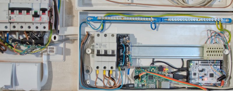
Clearly, [Tomasz Salwach] had raw data in mind as a design goal, and his Raspberry Pi-based meter delivers. After harvesting current sensing transformers from a bucket of defunct power meter PC boards, [Tomasz] calibrated them with a DIY oscilloscope and wired them and the voltage sensors up to an STM32 Nucleo development board. Data from the MCU goes to the Pi for processing and display as snazzy charts and GUI elements served internally. [Tomasz] was kind enough to include a link to his meter in his tip line post, but asked that we not share it publicly lest HaD readers love the Pi to death. But we can assure you that it works, and it’s kind of fun to peek in on the power usage of a house in Poland in real time.
It’s a nice project that does exactly what it set out to do. But if you missed the recent spate of Nixie-based displays, check out this front hallway meter or this one for a solar-power company CEO’s desk.


Not sure if this is the place to post, but I don’t know about anywhere else. I submitted my project a few weeks ago, and again a little while after that, but unfortunately, I haven’t received a response to either email. If you don’t want to feature it that’s fine, I’m just curious why. (Mine was the drone defense system)
Heck, I want to see that
Sometimes (I think) things are in the pipeline, but it would be nice to receive ack.
I agree. Just a simple response, like “We have received your tip, but it might be a few weeks/months before we publish it. Thanks” so we at least know it didn’t end up in the Spam folder. :)
Polish programmers have excellent skills and are cheaper than Indians :)
It’s not just a case of cheaper, it’s a case of better. A lot of Indian work is sub-par.
These are amazing generalizations! ^_^
Would be interested in the type of current transformer used as I have identical ones but designed for kHz regime… a simple sketch of the current sense part would have been nice as a contribution as there are so many techniques…
Nice build anyway, I have to reproduce this one for a long time, and I only scavenged my CTs a couple months ago… time to grab a PIC and interface some op-amps, and feed my raspi from SPI :)
This project is more about software than hardware.
You can use almost any current transformer, one like this here:
http://openenergymonitor.org/emon/buildingblocks/report-yhdc-sct-013-000-current-transformer
Or similar one of that in my project – You may look at Talema AC1075.
Connection to MCU is same as in this project:
http://openenergymonitor.org/emon/buildingblocks/measuring-voltage-with-an-acac-power-adapter
Probably just me… but in that photo, shouldn’t there be more physical separation between the ~220V, the voltage sensing gear transformer headers (perhaps some heat shrink?) and the pi board, including its 5V input lead?
… the current and voltage sense wiring, if one of the solder joints should fail, there doesn’t seem to be a lot to stop one of the leads potentially brushing up against mains.
Assume photos are from initial stage before things were cleaned up for long term use?
That’s not to say that this isn’t a pretty impressive re-use of electronics etc.. The proximity of directly soldered wires to mains voltage just concerns me a little.
First we can discuss worst-case scenario – a short of AC live and MCU inputs.
MCU GND is connected to PE wire.
I think in case of short of this kind:
1. Thin wires will vaporize
2. RCB and/or overcurrent breaker will switch off AC circuit
3. No fire but complete damage to MCU and RPi.
But this is unlikely to happen, because, there’s no vibration, temperature change and even human intervention there.
How often You will open those boxes?
Transformers are rated for more than 2 kV insulation.
Primaries of voltage transformers are soldered to wires and glued to insulate and for mechanical stability.
And it’s not a finished product in any kind. Yours installation will be different, and You can use connections of Your choice.
Probably some of the local electrical code would require a physical partition and higher voltage rating for the low voltage stuff inside the same electrical box.
The safety people also don’t like to see wires vaporizing instead of proper fuses to go first.
AFAIK Local Electric Code generally only applies to people professionally doing things.
My Homeowners Insurance doesn’t cover the item that caused the damage, IE they fix the damage from the broken pipe, but not the broken pipe itself.
In the UK, the domestic electricity regulations (Part P) apply irrespective of who is doing the work. A home owner is legally allowed to do certain small jobs.
The house insurance could be invalidated if you install unapproved (non-standards compliant) equipment, and that equipment is found to have caused the damage, eg a fire.
visible copper at the bottom of the MCBs
resistors soldered inline in the consumer unit
box on the right has neutral and earth bars because its a stripped out consumer unit too, partly explains why its unnecessarily huge.
is the pi even held in place? looks like its in a transparent case but the usb lead goes behind it.
not great when you are playing with mains.
The distortion on the voltage transformers may be reduced by adding a (dummy) load on the secondary side.
Checkout http://volkszaehler.org for a (German) smart meter implementation taht offers both hardware and software components for a variety of meters.