Throwing a 5V regulator like the LM7805 at our projects can become habit forming, after all they’re dirt cheap and the circuit is about as basic as they come with only two external components, an input and output cap. As this is a good enough solution to most of our 5V circuits we can come into some issues if we aren’t paying attention. Linear regulators can only dissipate so much power in the form of heat before they need a heat sink and/or active cooling. Even if they can produce a cleaner output, in an embedded system, large power losses to heat are less than ideal to say the least.
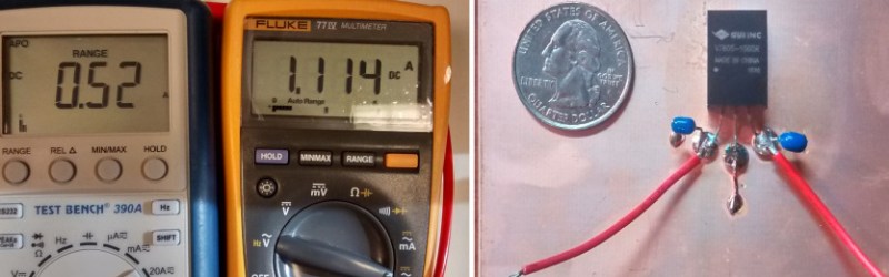
[Daniel] needed an efficient solution to use in the place of an LM7805, after looking at the drop-in replacement switching solutions available on Adafruit’s website, he headed to DigiKey for a similar and less expensive part. [Daniel] collected some data and found the regulator to be 92% efficient with a 12V input, which is not quite the claimed 97% but a good solution nonetheless.
Switching voltage regulators are nothing new, so don’t even act like we just jumped on this switch-mode bandwagon! But it pays to give a little thought to your power supply. And while you’re in the mood, have an extremely thorough look inside the LM7805.


How much noisier (if at all) are these switching regulators?
I ask because I have a project that senses signals of about 6 pA (roughly a couple of millivolts) which is about 3x the noise floor.
A switching supply from a PC is too noisy for my application, but a 7812 with proper caps works. (As will most bench supplies.)
What I’ve found is if you pile enough caps on the output you can quiet a switcher down, but you can also use a switcher for the big voltage drop, and then a linear LDO to get the final voltage, and still have something in excess of 80% efficiency.
Figure of merit for your LDO: PSRR
(You probably know this, but if anyone else doesn’t, look for this in the datasheet when choosing your LDO.(
A little inductance goes a long way.
Those days are gone for the most part.
Putting an inductor or CMC in your power path?
God I hope not.
Analog in general? Sadly yes. Myself included.
When a building (actually one floor of a building) was being retrofitted for our use, in the early 1990’s, several large inductors (the cabinet was approximately 2x3x3 feet in size) were installed in power closets to condition the mains. All the switch mode power supplies in our mid-frames, workstations, and PCs resulted in an almost square wave on the mains. These inductors, (the cabinets were warm to the touch) helped smooth it back out.
I would be very very surprised if you can use anything that ‘switches’ if you only have a couple of dB from the noise floor.
Back in the 90s we designed a set-top box – analog TV of course – and dropped a switcher in to replace a 7805 as we had to switch tuner modules and the new one drew more current. The pin-compatible switcher was so noisy all sorts of crap could be seen on the picture no matter how many Cs and Is we the at it.
Yup. Sometimes you just can’t filter out enough of the garbage (I’m a radio hobbyist), which is why I tend to stick to linear regulators. Most of my projects are bulky enough to handle having a heat sink, so no problems there. Some switchers are okay, but most are just RFI pumps.
Look at replacements in vintage gaming consoles. Often they introduce a fair bit of noise into the picture (and occasionally audio) signals. It’s one of the bigger problems we encounter when trying to make our systems more efficient and produce less heat.
Good info to make sure everyone has :)
Efficiency is a great metric, but I find that those numbers don’t get across the message the way that INefficiency numbers do. For example, the switching converter might dissipate 0.5W for a 1A load, while the linear regulator will dissipate 7W. That’s 14 times the wasted power! And 14 times more heat to handle, in the same space. Way more impact than 42% versus 90% efficiency.
How do you get 14 times?
The input power for 42% versus 90% efficiency for the same net output power has a ratio of 2.16 to 1
I think those are just made up numbers. The point he was trying to make was it is more dramatic to say you are wasting 5.8 times as much power than saying you are using 2.16 as much power or quoting percentages. Human psychology stuff.
They are not made up. Uout = 5V, Uin = 12V, Iout = 1A, Pout = 5W
With the linear regulator: Iin = 1A, Pin = 12W (5/12 = 41.67% efficiency). So Pdisp = Pout – Pin = 7W (dissipated “wasted” power)
With a 90.9% switching regulator, Pin = 5.5W, Pout = 5.0W. So Pdisp = Pout – Pin = 0.5W.
So 14 time more wasted power (7W vs. 0.5W)… And 14 time more power to dissipate from the regulator… (So more more heatsink cost, increase of temperature into the case, reducing of chemical capacitor lifetime etc…)
The efficiency is not calculated on the output, but on the input side.
So LDO: 12V/1A = 12W in –> 5W out = 41,6%
And Switching: 12V/1A = 12W in –> 10,908W out = 90,9%
That makes 5W to 10,9W and 41,6% to 90,9%.
At least, that’s why it was confusing to hear 14 times more loss. But design wise,
you were absolutely right, you always look on the output, not on the input.
Right, the numbers aren’t made up. The actual equipment in this article is wasting 14 times less than the linear regulator would. It’s just useful when getting across the reason to use a switching supply to someone who doesn’t understand why you wouldn’t just throw on a 7805.
It also illustrates ANOTHER psychological perception that has been used as a marketing trick for the switching regulator above. Even the Hackaday editor says 92% efficiency is no big deal compared to the claimed 97% efficiency (which is only possible under ideal conditions, minimum input voltage, etc). But that’s 8% loss versus 3% loss…under typical conditions, the regulator will waste three times the energy implied by the manufacturer’s advertised front-and-center efficiency figure.
What can be the expected quiescent current on those? Datasheet does not mention.
Would a switcher like this or an LDO like TPS7A6550-Q1 with a quiescent current of 20 uA be preferrable for a long-running battery powered project?
Depends on your current consumption distribution. Is it always on and sucking 50mA, or is it 99.9% idle with a few microamps? If the latter, you will have other problems like the decoupling capacitor leakage becoming a significant contribution to your power loss.
…and shop around for your low quiescent current regulator, too. For a battery-powered device one of the regulators made by Holtek (for instance, the HT7333) might be a good bet; the quiescent current is in single-figure uA. They tend to have a fairly low input voltage rating though, so they’re good for batteries, but may not be suitable for mains-powered devices.
When shopping around for these type of devices I noticed most were in the few mA range so not very good in an always-on battery situation.
only 10x more expensive than something like this: http://www.ebay.com/itm/400760852729 or http://www.ebay.com/itm/291501116158
“Output Current: lowering the value of 3A, long 1.8A”
so.. all your base belong to us right?
What would be the best regulator to use to power a microcontroller at 5v if I already have mains vintage on the board (240v here in the UK)?
I am thinking of an IoT application which will switch mains and don’t really want to have to plug in a wall wart too.
Look at something like the iW1700. It has an extremely low quiescent current under no-load conditions (when your micro is in deep sleep). It was designed for applications like phone/tablet chargers, so the output power is fairly limited. ITead Studio is currently selling a 5v/500ma isolated supply based on this chip for $2.50 + shipping. Their own IoT mains switching units use basically the same thing in a different PCB.
I wouldn’t use one of these switching regulators, as they are not isolated, and the data sheet says its input voltage should be 6.5V-28V.
Where did you get the idea that they’re not isolated? The iW1700 is a primary-side switcher.
http://www.dialog-semiconductor.com/products/power-conversion/acdc-chargers-adapters/iw1700
I was actually referring the the switcher discussed in the article. The commenting system on here is a little confusing.
If you have to ask that question, do yourself a favour and quit now. It’s most likely your own life that you’ll be saving. 240V can be a life-changing experience. But to answer your question, fuse->20:1 transformer->full wave bridge rectifier->7805 equivalent regulator is a good starting point.
I want to see characterization of the switching noise … At anything over 750mA I always put atleast 220uF across the end
The noise coupled over to the input is good to know also
These would be useful in my mind for digital stuff or to drop the voltage down to reduce heat on a 78xx
I’ve used the exact part before and the switching noise on these particular 78xx replacements is remarkably low. (mini *isolated* switchers on the other hand…) Couldn’t see any switching hash with my oscilloscope AC coupled and set to the 1mv range. (just some milivolts of ripple at ~400KHz from the buck regulator) These regulators will also down-regulate and back-feed power if you’ve done something funky with your circuit. (saved my butt once) They are also *rated* for use as inverting power supplies, though most little buck regulators can do this trick too. (i.e. +12 to -5v etc)
Most of those 3 terminal switchers, are even noisier if you also run them with a low load, the spectrum of hash they inject onto the source and load lines has to be seen to be believed. Have fun!
I don’t quite get these concerns regarding noise. You want DC on the output and they produce (fairly) high frequency noise — that should be easy to filter, much easier at least than the 50/60Hz from mains via a simple transfomer and a linear regulator.
Could someone please clarify?
I think the trouble comes from parasitic paths. You can design a filter that has the necessary rejection but the fields couple all over
not just noise on the power lines, but noise generated in the RF and radiated. most of the time with RF projects, switching is NOT the best choice as they are noise as all get out in the RF spectrum.
That’s where proper shielding comes into equation. As I can see measurement equipment manufactrurers use switching power supplies in their osciloscopes, spectrum analyzers and waveform generators. If it’s good enough for them …
Essentially the PWM duty needed for the regulation determines how often the 2 MOSFET in a H bridge switches and hence their contribution of losses. The claimed efficiency is measured off a different voltage (i.e duty cycle), so that could account for the differences.
A good datasheet would have a family of efficiency curves (typ. values) that covers the input range (and output voltage) and that would give yo u a better guesstimate. Don’t relies on a single value because it doesn’t work that way.
I’ve used and OKI-78SR-5/1.5-W36-C drop-in replacement for an lm7805, it’s a bit cheaper than the one mentioned in the article (and doesn’t even require external caps, according to the datasheet):
http://www.mouser.com/ProductDetail/Murata-Power-Solutions/OKI-78SR-5-15-W36-C/?qs=uJpRT2lXVNXJP%252bo08dQqJQ%3D%3D
For those of you looking for 7805 replacements in less noise-sensitive applications, I found some less-than-50-cent (in qty. 10) adjustable output switcher PCBs on eBay (with inductors and everything on the board). The ones I got were based around the MP2307DN switcher. What I then did was remove the potentiometer (because they’re crap), and replaced them with 0603 36K resistors. All the cheapie boards use 8.2K for the feedback resistor to GND, and the feedback voltage on those switchers is 0.925V, and when I slapped the 36K on there, bam, 4.99V output according to my voltmeter. Since I was working with stuff that works with a 5V +/- 10% supply anyway (but draws about 0.5A total), I was thrilled. Then I just wired it to a little piece of veroboard with a 3 pin right-angle and slapped it right in where the 7805 went. Runs MUCH cooler, and total part cost was like 50-60 cents, as opposed to those crazy expensive ready-made 7805 solutions. Making 5 of them took me maybe 5 minutes total, so it seemed like a reasonable use of time.
I’m thinking I might 3D print little bumper cases to cover the sensitive bits (i.e. stuff I might short) and wrap the thing in foil for shielding, but I’m not sure it’s necessary (it’s not for a commercial project or anything — I had an old NES where the 7805 died somehow, and rather than replace it with a 7805, I thought I’d keep it a little cooler this way)
Do all of this on hackaday.io or on YouTube and I’ll expect to see your project on Hackaday someday soon :)
Eh, been there, done that ;)
http://hackaday.com/2014/10/10/a-pc-engine-to-turbografx-16-converter/
(And hey, it even had something to do with video games!)
So, in other words you replaced a quiet LDO with a buck converter with the worst possible grounding paths for generating RFI, and you’re surprised?
Golly, it’s a high frequency oscillator standing 1 inch above a ground plane, sounds like an antenna.
What is the shape of the high current path? A loop?
Is the inductor in the smps at least shielded?
The purpose of a filter, any filter is to provide an impedance mismatch. What is the SRF of the inductor? How about any decoupling caps?
Yep. For better electrical efficiency.
A quiet LDO that’s hotter than the blazing fires of hell, mind you. At 1A with a 7V drop, I don’t think there’s enough surface area on the thing to get a heatsink big enough to dissipate 7W. I’d personally never use one connected to a supply that provides more than, say, 7V.
If it was really an issue, I’d shield the heck out of the switching supply, have it drop the 12V to ~7V (with an adjustable), and then use the 7805 for the last mile. (In fact, I do this on a design for a voltage tester I made for a coworker, and it’s quite stable and clean.)
I’m seeing a 5 degrees C / Watt junction to case thermal resistance in the LM7805 datasheet.
7 watts * 5 deg c / watt = a 35 degree C temperature rise assuming an infinite heatsink.
If low-noise is needed, this can be cooled properly.
Still, raising the temperature by 35C for a sizable area of the design is not an option for many designs, and there’s still 7W of heat that needs to go somewhere. 7W in that limited of a space cannot be solved just by a heatsink, and even with active cooling, it can be an issue. (7W is heading into the “needs a CPU heatsink/fan” range, and those often have more area of contact.) It can be done, but the design should not be based around your choice of voltage regulation.
Low noise can be achieved by a number of means. Proper shielding and grounding is much more important in many cases than whether or not there’s a switching regulator in the path. Again, my recommendation would be to put a well shielded switching regulator before the LDO, to get the best of both. Most off-the-shelf input supplies are going to be noisy anyway, so there’s often a need to clean that up regardless, and the incoming voltage to the LDO linear regulator can be adjusted to minimize the heat. It might even make the resultant design smaller.
Come on HaD. If you know what you are doing there is no such thing as a switch-mode “drop-in replacement” for a linear regulator – and vice-versa. Let’s move past the “Maker” level when writing these posts HaD.
It depends on the application. Almost nothing is a “drop-in replacement” for every single application — even if the spec sheet says they’re the same, the implementation could be just so that brand X’s device operates differently from brand Y’s when used on a particular design.
If the application is “I need to power a bunch of 7400 logic ICs that have a max Vcc of +5V, but all I have is this +12V brick” then yes, it is likely to work as a drop-in replacement. If the design involves sensitive radio equipment, it’s probably unlikely to work as a drop-in.
I think the article does a reasonable job of explaining when you might want to consider switching from a linear to a switcher. And obviously, if there’s a reason to choose one over the other, then it’s not EQUIVALENT, even if it does just drop in and replace the other device (i.e. it is a “drop in replacement”).
It will work in RF applications. Just add lots and lots of shields and some decent filter. Or shield your sensitive device, because RF noise will come from any modern wall wart. Most of them are SMPS designed in China anyway, so be prepared…