The Raspberry Pi is a very capable device whose hardware has been pushed to the limit in all sorts of interesting ways. But even the most ingenious of experimenters have to agree on one point; it doesn’t possess an analog-to-digital converter. If you want analog inputs you will have to buy or build them.
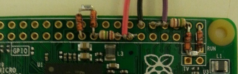
[Mincepi] has done just that, but not as you might expect by adding an integrated circuit on one of the Pi’s interfaces. Instead the circuit [Mincepi] is using consists only of passive components, measuring the time taken to discharge the parasitic capacitance of one of the Pi’s inputs from logic 1 voltage to logic 0 voltage through a resistor into the voltage to be measured. This is a long-established approach to A to D conversion, one that was achieved back in the day with purpose-designed timers as microprocessor ancillaries.
The problem is that the Pi does not have a timer peripheral, so [Mincepi] has used the shift registers that form part of the Pi’s SPI and PCM inputs to perform this task on two channels. A sample rate of 100kHz and 6-bit resolution is claimed, with enough voltage range for a 1V peak-to-peak audio signal to be sampled.
Of course, simplicity does not guarantee a good ADC, and this circuit does not perform very well. It is noisy, non-linear, and as [Mincepi] puts it, probably sensitive to temperature. And though [Mincepi] talks in detail about the software to drive it, none is forthcoming. To quote: “It doesn’t include code since I’m in the process of writing a proper sound device module. My previous code was a simple character device, but it worked just fine, and served to prove the concept.”
We really want this to work, even if it’s not the best ADC ever. So we eagerly await the sound device module, and look forward to more news from the project.
This may be the simplest of simple ADCs we’ve yet featured here on Hackaday, but it’s not the first we’ve seen. There is this one using a comparator for example, or this one using a flip-flop. It is the essence of creative electronics to eke a function from a component that was never meant to be, please keep them coming!


So this is effectively a Successive approximation ADC
https://en.wikipedia.org/wiki/Successive_approximation_ADC
I can’t see the similarity.
If simplicity is the objective, it can be done either with a resistor ladder like the old parallel port “sound cards”, using lots of IO or a shift register, perhaps one that can load all the bits together after shifting them in, but being fairly simple to implement or a capacitor on a pin maybe with some transistor switching, not as easy to build but can be controlled by sending pwm as it smooths out the signal. Although it does mean you have to manipulate the pin all the time or the voltage will peg 0/1 depending on the configuration. Where as the resistor ladder can hold a voltage and the pins can be set and left.
There are other ways but These two seem fairly relevant in this case.
That’d be a DAC, this is an ADC! Although if you add a comparator, a DAC can function as successive-approximation ADC. But this is very different from that.
No, pretty sure it’s a voltage-to-time convertor. It was used in the analogue joystick port on PCs, back when they had them, and the analogue paddles for the Atari 2600. Among others.
They discharged a capacitor to 0V, then connected it to 5V through the pot in the analogue joystick. The amount of time it takes to charge to 5V, tells you the position of the pot. You read it by constantly checking the capacitor and keeping track of the time.
Only this is a bit different cos there’s no 5V. Took me a minute to understand, in this case the capacitor is the instrinsic capacitance on a Pi’s pin, and he’s setting it to 5V (or 3.3V or whatever a Pi runs on), then switching it to input and seeing how long it takes to discharge to 0V.
Except not quite 0V. It’s actually CMOS logic 0, which is about half the supply voltage. It doesn’t actually matter what the threshold voltage is, only that it’s consistent. This is why it’s limited to measuring about 1V, it can only measure voltages low enough to count as logic 0.
I think. Pretty clever!
One nit-pick: the CMOS logic 0 is very close to 0 V. The threshold between 0 and 1 is about VDD / 2, but if you look at an actual output of a 74Cxx, 0 is close to 0 V, and 1 is close to 5 V.
Well, even Adafruit included photoresistor+capacitor into their Raspberry Pi Starter kit back then. It’s not new, though the ‘parasitic capacitance’ part in this approach is new to me – never saw it used for this task =)
It looks like timing the cycling of a relaxation oscillator
Nice out of the box thinking!
Nice try, but i don’t really trust the input parasitic capacitor and the threshold level,
so i will keep on using MAX11105 or like, which are 12bits 2MS/s SPI A/D in a 6 pin package, <3€.
But perhaps, RPI users are so penny-pinching ?
Or perhaps that particular RPi user was in a hurry and had some resistors but not an ADC chip?
So your issue is that this IS a hack?
As long as the parasitic cap and threshold level are consistent on that particular pin, on that particular Pi, it’ll be OK. Might need re-calibrating if he used another pin, or somebody else uses it on their own Pi. Or it might not, might be they’re consistent values across every Pi.
Way to find out would be some guy with several Pis, or several guys with one Pi, all comparing the values against a multimeter for a variable voltage. An AA battery with a pot for a voltage divider would do as an input.
We have a name for penny-pinching Raspberry Pi users: Arduino users. It’s really a small matter, if the parasitic capacitance proves to be unpredictable, to put a high-quality fixed capacitor to ground on the pin in question. ‘Course, this works better on an Atmel MCU.
How exactly is a diode a passive component?
+1
“Passive” is a slippery word.
Technopedia says, “A passive component is a module that does not require energy to operate, except for the available alternating current (AC) circuit that it is connected to. A passive module is not capable of power gain and is not a source of energy.” This definition would include diodes. Not sure why they bring AC into the definition, and I know of no component that does not require energy to operate. For example, a resistor can be used to convert a voltage to a current or vice-versa, but for it to do either, there has to be current flow, which requires energy. A capacitor converts dV/dt into current, but this requires a change of voltage and a current, again requiring energy.
Wikipedia goes a little further, but is basically just an expansion of Technopedia’s definition (including the “AC” part). It classifies tunnel diodes as active, but does not make a judgment on other types of diodes.
Wikitronics says that a passive component is one that cannot produce gain.
However, using only a carbon granule microphone, a loudspeaker, and a battery, you can produce enough feedback to cause oscillation, which requires gain. Since neither the battery nor the speaker have gain, this leaves the pressure-variable resistor (the carbon microphone) as the gain element. So a variable resistor can be an active component, just as a tunnel diode can be an active component (these can produce oscillation with no other active components involved). Likewise, you might think of a neon lamp as a passive component, but these can be made into a circuit along with a resistor, capacitor, and battery to also form an oscillator.
A more functional definition of passive system would be one that requires no power source other than the incoming signal to operate. In this sense, it is the circuit as a whole that is either passive or active, rather than the components. A crystal radio is a passive circuit, even though it uses a diode and can be used as a source of energy, as long as you don’t need a lot of energy.
Along with the new Pixel Gun 3D per trucchi you’ll be able to develop a carddeck in the matter of no time. With this trick you can now obtain the best cards in under a month. Normally it would take more than 5 months or alot of money to obtain the amount of cards that you need to create a strong deck. This why we suggest anyone to utilize this tool.