Storing Image Data As Analog Audio

Ham radio operators may be familiar with slow-scan television (SSTV) where an image is sent out over the airwaves to be received, decoded, and displayed on a computer monitor by other radio operators. It’s a niche mode that isn’t as popular as modern digital modes like FT8, but it still has its proponents. SSTV isn’t only confined to the radio, though. [BLANCHARD Jordan] used this encoding method to store digital images on a cassette tape in a custom-built tape deck for future playback and viewing.

The self-contained device first uses an ESP32 and its associated camera module to take a picture, with a screen that shows the current view of the camera as the picture is being taken. In this way it’s fairly similar to any semi-modern digital camera. From there, though, it starts to diverge from a typical digital camera. The digital image is converted first to analog and then stored as audio on a standard cassette tape, which is included in the module in lieu of something like an SD card.

To view the saved images, the tape is played back and the audio signal captured by an RP2040. It employs a number of methods to ensure that the reconstructed image is faithful to the original, but the final image displays the classic SSTV look that these images tend to have as a result of the analog media. As a bonus feature, the camera can use a serial connection to another computer to offload this final processing step.

We’ve been seeing a number of digital-to-analog projects lately, and whether that’s as a result of nostalgia for the 80s and 90s, as pushback against an increasingly invasive digital world, or simply an ongoing trend in the maker space, we’re here for it. Some of our favorites are this tape deck that streams from a Bluetooth source, applying that classic cassette sound, and this musical instrument which uses a cassette tape to generate all of its sounds.

Approximating An ADC With Successive Approximation

[Igor] made a VU meter with LEDs using 8 LEDs and 8 comparators. This is a fast way to get one of 8 bits to indicate an input voltage, but that’s only the equivalent of a 3-bit analog to digital converter (ADC). To get more bits, you have to use a smarter technique, such as successive approximation. He shows a chip that uses that technique internally and then shows how you can make one without using the chip.

The idea is simple. You essentially build a specialized counter and use it to generate a voltage that will perform a binary search on an unknown input signal. For example, assuming a 5 V reference, you will guess 2.5 V first. If the voltage is lower, your next guess will be 1.25 V. If 2.5 was the low voltage, your next guess will be 3.75 V.

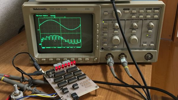
The process repeats until you get all the bits. You can do this with a microcontroller or, as [Igor] shows, with a shift register quite simply. Of course, you can also buy the whole function on a chip like the one he shows at the start of the video. The downside, of course, is the converter is relatively slow, requiring some amount of time for each bit. The input voltage also needs to stay stable over the conversion period. That’s not always a problem, of course.

If that explanation didn’t make sense, watch the video. An oscilloscope trace is often worth at least 1,000 words.

There are, of course, many ways to do such a conversion. Of course, when you start trying to really figure out how many bits of resolution you have or need, it gets tricky pretty fast.

Continue reading “Approximating An ADC With Successive Approximation”

STM32 Oscilloscope Uses All The Features

[jgpeiro] is no slouch when it comes to building small, affordable oscilloscopes out of common microcontrollers. His most recent, based on an RP2040 with two channels that ran at 100 MSps, put it on the order of plenty of commercially-available oscilloscopes at this sample rate but at a fraction of the price. He wanted to improve on the design though, making a smaller unit with a greatly reduced bill-of-materials and with a more streamlined design, so he came up with this STM32-based oscilloscope.

The goal of this project was to base as many of the functions around the built-in capabilities of the STM32 as possible, so in addition to the four input channels and two output channels running at 1 MHz, the microcontroller also drives a TFT display which has been limited to 20 frames per second to save processor power for other tasks. The microcontroller also has a number of built-in operational amplifiers which are used as programmable gain amplifiers, further reducing the amount of support circuitry needed on the PCB while at the same time greatly improving the scope’s capabilities.

In fact, the only parts of consequence outside of the STM32, the power supply, and the screen are the inclusion of two operational amplifiers included to protect the input channels from overvoltage events. It’s an impressive build in a small form factor, and we’d say the design goal of keeping the parts count low has been met as well. If you do need something a little faster though, his RP2040-based oscilloscope is definitely worth checking out.

Continue reading “STM32 Oscilloscope Uses All The Features”

Successive approximation register ADC

Homebrew Circuit Explores The Mysteries Of Analog-to-Digital Conversion

When it comes to getting signals from an analog world into our computers, most of us don’t give much thought to how the hardware that does the job works. But as it turns out, there are a number of ways to skin the analog to digital conversion cat, and building your own homebrew successive approximation register ADC is a great way to dispel some of the mystery.

From his description of the project, it’s clear that [Mitsuru Yamada] wasn’t looking to build a practical ADC, but was more interested in what he could learn by rolling his own. A successive approximation register ADC works by quickly cycling through all possible voltage levels in its input range, eventually zeroing in on the voltage of the input signal at that moment and outputting its digital representation. The video below shows how the SAR ADC works visually, using an oscilloscope to show both the input voltage and the output of the internal R-2R DAC. The ADC has an input range of 0 V to 5 V and seven bits of resolution and uses nothing but commonly available 74xx series logic chips and a couple of easily sourced analogs for the sample-hold and comparator section. And as usual with one of his projects, the build quality and workmanship are impeccable.

We love these sorts of projects, which are undertaken simply for the joy of building something and learning how it works. For more of [Yamada-san]’s projects, check out his 6502-based RPN calculator, or the serial terminal that should have been.

Continue reading “Homebrew Circuit Explores The Mysteries Of Analog-to-Digital Conversion”

Raspberry Pi Pico ADC Characterized

[Markomo] didn’t find much useful information about the Raspberry Pi PIco’s analog to digital converter, so he decided to do some tests to characterize it. Lucky for us, he documented the findings and shared them. The results are in a series of blog posts that cover power supply noise, input-referred noise, signal to noise ratio, and distortions.

There are some surprising results. For example, the Pico’s low noise regulator mode appears to produce more noise than having it set for normal operation. There also appears to be a large spike in nonlinearity around certain measurements.

Continue reading “Raspberry Pi Pico ADC Characterized”

A Complete Raspberry Pi Power Monitoring System

As the world has become more environmentally conscious, we’ve seen an uptick in projects that monitor or control home energy use. At a minimum one of these setups involves a microcontroller and some kind of clamp-on current sensor, but if you’re looking for resources to take things a bit farther, this Raspberry Pi energy monitoring system created by [David00] would be a great place to start.

This project includes provides software and hardware to be used in conjunction with the Raspberry Pi to keep tabs on not just home energy consumption, but also production if your home has a solar array or other method of generating its own power. Data is pulled every 0.5 seconds from a MCP3008 ADC connected to up to five six current sensors to provide real-time utilization statistics, and visualized with Grafana so you can see all of the information at a glance.

While [David00] has already done the community a great service by releasing the hardware and software under an open source license, he’s also produced some absolutely phenomenal documentation for the project that’s really a valuable resource for anyone who wants to roll their own monitoring system. He’s even offering hardware kits for anyone who’s more interested in experimenting with the software side of things than building the PCB.

Home energy monitoring projects are certainly nothing new, but the incredible advances we’ve seen in the type of hardware and software available for DIY projects over the last decade has really pushed the state-of-the-art forward. With so many fantastic resources available now, the only thing standing between you and your own home energy monitoring dashboard is desire and a long weekend.

When Is A 10-bit A/D An 8-bit A/D?

Marketing guys love bigger numbers. Bigger is better, right? After all, Subway called it a “footlong” not an 11-incher. So when it comes to analog to digital (A/D) conversion, more bits are better, right? Well, that depends. It is easy to understand that an A/D will have a low and high measurement and the low will be zero counts and the high will result in the maximum count for the number of bits. That is, an 8-bit device will top out at 255, a 10-bit at 1023, and so on.

The question is: are those bits meaningful? The answer depends on a few factors. Like most components we deal with, our ideal model isn’t reality, but maybe it is close enough.

Continue reading “When Is A 10-bit A/D An 8-bit A/D?”