We recently posted a three-part series about using LTSpice to simulate electronic circuits (one, two, three). You might have found yourself wondering: Can you really simulate practical designs with the program? This quick analysis of [QRP Gaijin’s] minimalist regenerative receiver says “yes”.
The stated goals for the receiver design (from [Gaijins] post) are:
- Design and implement a minimalist but practically usable regenerative receiver capable of HF reception from 3-30 MHz.
- Analyze the key aspects of the receiver’s operation (e.g. behavior of the regenerative detector, gain and frequency response of the AF amplifier) using the circuit simulation tool LTspice.
- Explain the design and explaining the LTspice analysis techniques in enough detail that the interested reader can reproduce the simulation results. Also, provide several references to improved designs for regenerative detectors or regenerative receivers.
LTSpice modeled the radio’s regeneration control, the stability of the detector, and the audio amplifier. The radio built entirely out of 2N3904 transistors (and a varactor for tuning capacitance) works as expected.
We covered [QRP Gaijin’s] diary when he was building an early version of this radio. Having all of it in one place and expanded is welcome, though. This may not be the prettiest regenerative receiver we’ve covered, but it is surely the best analyzed, and it makes a great example of using LTSpice with a practical project.


A great example indeed. It’s not easy to do pspice in a way that produces useful and/or accurate results. Especially for high frequencies.
“A great example indeed. It’s not easy to do pspice in a way that produces useful and/or accurate results. Especially for high frequencies.”
Given two otherwise identical SPICE simulations, one at a low frequency and one at a high frequency, both will take identical time and resources to run. The only way the two simulations would take different time and resources to run is if you added more to one and not the other – such as adding more parasitic parameters to the high frequency simulation.
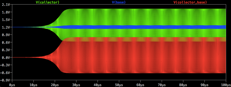
That’s one of the “interesting” (or annoying) things about simulating regenerative receivers: significant events are happening at vastly different timescales: the regenerative detector, if oscillating, is swinging up and down at a microsecond-level timescale, whereas the AF detection/smoothing takes place on a millisecond-level timescale. For accurate simulation you have to be able to resolve the microsecond-level features, which requires a huge number of timesteps in order to observe the millisecond-level events.
That wouldn’t be so bad by itself, but what gets even worse is when you are injecting signals into the tank to simulate input RF signals perturbing the regenerative detector’s oscillation. If your injected signal is only slightly off frequency from the simulated oscillation frequency of the detector, you will get a beat note (just as you do in real life). But that’s usually not what you want: usually, you want to analyze the amount of regenerative amplification that is provided for a signal that exactly matches the tank’s oscillation frequency (the frequency of maximum regenerative gain). But the problem is that because this is a simulated system (that takes several minutes to run) with discrete aliasing artifacts, if the simulation timestep is too coarse there will be a simulator-induced phase shift in the dynamically-computed oscillator waveform, which will shift it away from the frequency of your injected signal (which is a perfect sinusoid at the specified frequency).
The way I usually do this is to use a very small timestep with no injected signal and to run an FFT to determine the actual simulated oscillation frequency. Then, inject a signal at exactly that frequency (RF) into the tank (via for example a transformer). If the frequencies match up closely enough, then you will see your injected RF waveform being regeneratively amplified, growing larger cycle by cycle. If the frequencies mismatch, you will get an AF modulation riding on top of the RF, corresponding to the beat note frequency.
Probably more than you wanted to know. :-)
My impression is that ‘qrp’s’ post is a ‘look at me…look at me”. In practice….cods!…The regen receiver is a breeze to use. One should not be deterred by the nonsense written above about ‘technical analysis’ presumably to enable the writer to feel fulfilled. You will quickly learn that either side of oscillation ( controlled by capacitor or potentiometer depending on circuit is a point of maxuimum amplification of signal less the ‘squeal’. We move off the ‘squeal’.. as that signal will be radiated. One or two broadband RF stages can inhibit that but it’s a point of ‘non operation’ for what we want from the receiver….comprehensible signals’
All other controls are no different from any SW receiver…Volume control , Tuning, perhaps separate tuning-Bandspread (more precise tuning around a spot chosen on the main/coarse tuning dial or ‘spot’.) Ignore all that humbug and just get to know your regen. It should take you 30 seons to a couple of minutes to be an expert.
I’d like to see Spice analysis of a Reflex Receiver: https://en.wikipedia.org/wiki/Reflex_receiver
With the same component amplifying both the RF and audio section, a simple frequency response plot won’t be enough.
Good question. I don’t have experience with reflex receivers so I can’t comment in detail. However, you should be able to gain useful insight by running a transient (time-domain) analysis and feeding in a modulated RF waveform into the input of the detector, and observing the detected AF at the output of the detector. You can vary RC time constants and biasing and such to see how they affect the detection efficiency, which will be reflected in the magnitude of the detected AF output.
At the Yahoo Group http://groups.yahoo.com/group/regenrx-simulations there are some LTspice models of some reflex-regenerative receivers (Spontaflex by Sir Douglas Hall) — see the “Files” section and look in the folder “John’s simulations”. There are also some discussions and examples on the list about how to simulate detector efficiency (i.e. how much AF output gets created for a given modulated RF input). So, for someone who understands reflex detector operation (not me), you should be able to use these materials as a starting point for deeper LTspice analysis of reflex receiver behavior.
Try simulating a dirt simple diode-ring double-balanced direct conversion receiver in SPICE. Even with carefully tweaked and optimized parameters, the simulation is painfully slow and eats up a large amount of storage. Spiky-edgy things are like that in SPICE. BTW, it’s SPICE in all-caps, not Spice. SPICE is an acronym for Simulation Program with Integrated Circuit Emphasis.
Check out the Spice home page.
http://bwrcs.eecs.berkeley.edu/Classes/IcBook/SPICE/
I noticed a spike in my blog traffic from Hackaday, so I came to check out this article. :)
For those interested in simulation of regenerative receivers, please see my small Yahoo Group at http://groups.yahoo.com/group/regenrx-simulations . There isn’t so much message traffic on the group, but you might be interested in the files section of the group, which has several LTspice models of regenerative receivers and detectors that can be downloaded, studied, simulated, and modified. You can even try building them in hardware! It seems that most people who build regenerative receivers aren’t interested in circuit simulation, but a few of us are. If this sounds like you, please have a look.
Oh please stop these click bait titles… I was so hoping in a detector made out of a nail and two dried Jalapeños :ø)
Know why he’s wearing gloves to tune it? Hand capacitance, I bet.
There’s no hand capacitance with this set, compared with some other sets I’ve built. I tested it up to about 15 MHz. The hand capacitance is minimized because the tuning is done by a varactor (not a tuning capacitor), so the control element (a ten-turn pot) carries only DC, not RF. Same goes for the regeneration control: it’s in a low-impedance part of the circuit (the RF across the pot is bypassed with a capacitor of a few nF), so there is basically no hand capacitance there either.
I guess there might be some hand capacitance issues at 30 MHz since I didn’t use a ground plane, and the floppy wires could lead to unwanted stray couplings. But up to 15 MHz, there’s no objectionable hand capacitance.
One thing I did notice is that the AF amp is prone to picking up and rectifying ambient electromagnetic noise (like that from my wifi router, or my cell phone) because everything is open and unshielded. My next build will probably use a ground plane — but it won’t be as compact as my 7-transistors-flush-against-each-other construction style. :-)
psst, typo in the title: “reciever”
Interesting thing is that no-one replicate his results to confirm how work.
I watch video and i am not impressed with what i see and heare.
Design of circuit is not good enough,it should be better to build it on metal ground plate with soldering points.
Then maybe we can expected some results.
I understand that qrp.gaijin is enthusiast but that is not enough,experimenting is not bad but if is
just for experimenting then that is nothing i mean if there is no purpose in practical circuit.
I am attempting to build this receiver right now… All the best…. Radionut63
I made comment on ‘qrp’s analysis but it vanished into ????….when posted. Is this the way it works here….monitoring? or do things just ‘disappear’.