Erasing EEPROMs Isn’t Always As Easy As It Seems

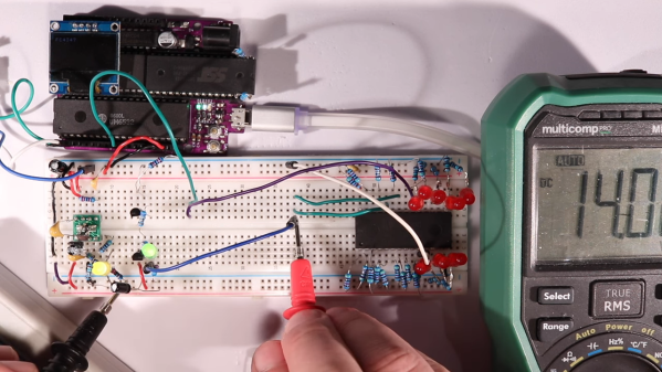
When is 14 volts not actually 14 volts? Given [Anders Nielsen]’s recent struggles with erasing an old-school EEPROM, it’s when you really need it that things tend to go pear-shaped.

A little background is perhaps in order. [Anders] is working on a scratch-built programmer for ROMs to complement his 65uino project, which puts a complete 6502 computer into the footprint of an Arduino Uno. He wisely started the ROM programmer project at the beginning, which was to generate the correct voltages for programming. This turned out to be not as easy as you might think thanks to the solderless breadboard’s parasitic effects on the MIC2288 switching boost regulator he chose.

The video below is a continuation of the programmer build, which ends up being just as fraught as the first part. Being able to generate the programming voltages is one thing; getting them onto the right pins at the right time using nothing but the 5-volt GPIOs on a microcontroller is another. In true retro fashion, [Anders] tackled that problem with a pair of small-signal transistors, which seemed to work once the resistor values were sorted, at least when applying a 12-volt signal intended to show the ROM’s hard-coded manufacturer ID on the data bus.

But erasing the ROM, which requires 14 volts while the chip enable line is held high for 100 ms, proved a little trickier. Despite multiple tries, the ROM wouldn’t erase thanks to the 14-volt rail being dragged down to around 9 volts. [Anders] fixed that with a new base resistor on the driver, to increase the current and keep the voltage up where it needs to be. Just goes to show you that the data sheets don’t always tell the whole story.

We’ve been enjoying the unfolding story of this programmer, and we’re looking forward to the next installment.

Continue reading “Erasing EEPROMs Isn’t Always As Easy As It Seems”

Pillaging The Wealth Of Information In A Datasheet

It’s a fair assumption that the majority of Hackaday readers will be used to working with electronic components, they are the life blood of so many of the projects featured here. In a lot of cases those projects will feature very common components, those which have become commoditized through appearing across an enormous breadth of applications. We become familiar with those components through repeated use, and we build on that familiarity when we create our own circuits using them.

All manufacturers of electronic components will publish a datasheet for those components. A document containing all the pertinent information for a designer, including numerical parameters, graphs showing their characteristics, physical and thermal parameters, and some application information where needed. Back in the day they would be published as big thick books containing for example the sheets for all the components of a particular type from a manufacturer, but now they are available very conveniently online in PDF format from manufacturer or wholesaler websites.

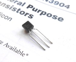
A 2N3904 in a TO92 through-hole package

Datasheets are a mine of information on the components they describe, but sometimes they can be rather impenetrable. There is a lot of information to be presented, indeed when the device in question is a highly integrated component such as a DSP or microprocessor the datasheet can resemble a medium-sized book. We’re sure that a lot of our readers will be completely at home in the pages of a datasheet, but equally it’s a concern that a section of the Hackaday audience will not be so familiar with them and will not receive their full benefit. Thus we’re going to examine and explain a datasheet in detail, and hopefully shed some light on what it contains.

The device whose datasheet we’ve chosen to put under the microscope is a transistor. The most basic building block of active semiconductor circuits, and the particular one we’ve chosen is a ubiquitous NPN signal transistor, the 2N3904. It’s been around for a very long time, having been introduced by Motorola in the 1960s, and has become the go-to device for a myriad circuits. You can buy 2N3904s made by a variety of manufacturers all of whom publish their own data sheets, but for the purposes of this article we’ll be using the PDF 2N3904 data sheet from ON Semiconductor, the spun-off former Motorola semiconductor division. You might find it worth your while opening this document in another window  or printing it out for reference alongside the rest of this article.

Let’s take a look at all the knowledge enshrined in this datasheet, and the engineering eye you sometimes need to assign meaning to those numbers, diagrams, and formulas.

Continue reading “Pillaging The Wealth Of Information In A Datasheet”

A Spicy Regenerative Reciever

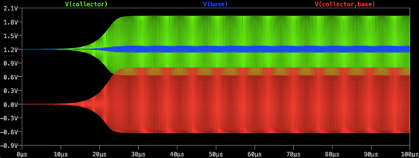
We recently posted a three-part series about using LTSpice to simulate electronic circuits (one, two, three). You might have found yourself wondering: Can you really simulate practical designs with the program? This quick analysis of [QRP Gaijin’s] minimalist regenerative receiver says “yes”.

Continue reading “A Spicy Regenerative Reciever”

Motion Activated Monitor Wakeup

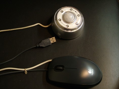
This hardware is used to keep a computer monitor awake when there is motion in the room. The monitor displays important information for firefighter in the vehicle bay, but only needs to be on when they are getting ready to go out on a call. The solution is a simple one, a PIR sensor combines with a mouse for motion sensitive input. When the PIR sensor detects motion it causes a mouse button click via a 2N3904 transistor. Now the monitor will not waste power or have burn-in over the long term, but whenever someone is in the room it will be displaying the information that the emergency workers need to know.

[Thanks Andy]