
Most of us didn’t fight in World War II, drive a race car, or fly the Space Shuttle. But with simulation, you can experience at least some of what it would be like to do those things. Granted, playing Call of Duty isn’t really the same as going to war. No matter what you are simulating, it only goes so far. However, you can get a lot of value from a simulation. I’d bet the average kid who has played Call of Duty knows more about WWII locales and weapons than my high school history teacher.
When it comes to electronics, simulation is an excellent way to get insight into a circuit’s operation. After all, most circuits operate in the abstract–you can’t look at an audio amplifier and see how it works without a tool like a scope. So simulation, when done well, can be very satisfying. You just have to be careful to remember that it isn’t always as good as the real thing.
That’s Spicy
One of the best-known electronics simulators is Spice, which Berkeley created in 1973. In its original form, you had to punch cards that described your circuit and the analysis you wanted to perform. Modern PC versions sometimes replace the deck of cards with a text file. The best modern versions, though, give you a GUI that allows you to draw a schematic and then probe it to see the results.
There are several paid and free versions of Spice (and other simulators) that include a GUI. One of the best for a casual user is the free offering from Linear Technology called LTSpice.
Linear makes LTSpice available and populates it with models for their devices in the hopes you’ll buy components from them. However, the software is entirely usable for anything, and it has a powerful set of features. Linear produces the software for Windows, but I can attest that it runs just fine under Wine on Linux. The Web site will invite you to register, but you don’t have to if you don’t want to.
Spice Quartet
There are four parts to working with Spice: The schematic capture (that is, getting the schematic in digital form), the simulation engine, the models, and the output. LTSpice is very easy to use for schematic capture, although some of it is a bit non-standard. For example, F9 is the undo key. There is no paste command. Instead, you select the copy tool (or hit F6) and then select the items you want to copy and drag them around. If you’ve used Eagle for PCB layout, it will remind you of that.
There’s a getting started guide (which is a bunch of PowerPoint slides) on the Linear site that you should probably read. You can also watch my quick demo below. The basic operation is pretty simple once you get used to the copy and paste or how to drag and drop existing components (hint: the open hand doesn’t move wires; the closed hand does).
DC Circuits
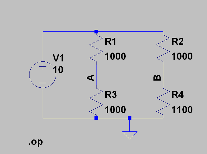 The video below shows how to build and analyze a very simple DC circuit (see right). You’ll see that once you get used to how LTSpice does commands, it is very easy to draw a circuit like that. One thing to note that I didn’t mention in the video: While I entered 1000 and 1100 for the resistor values, I could have also said 1k or 1.1k. Spice is smart enough to know about most prefixes like k (kilo), u (micro), and so on. The only confusing one is m. This is milli, not mega. If you want to put in, for example, a 5 megaohm resistor, try 5000k or 5meg. Using 5m, however, will give you .005 ohms, which is going to throw off your simulation quite a bit. The letters are not case-sensitive, so m and M are both milli.
Another tip: In the video, all the components are oriented in their default direction. However, when you are dragging an outline (either because you are adding a new component or dragging an existing one) you can press Control+R to rotate it by 90 degrees.
Just for point of comparison, the actual Spice “card deck” for this simple circuit looks like this:
R1 N001 A 1000
R2 N001 B 1000
R3 A 0 1000
R4 B 0 1100
V1 N001 0 10
.op
.backanno
.end
Not so hard to understand, but that’s because this is a very simple circuit. Imagine something with dozens or hundreds of components, and you’ll appreciate the LTSpice schematic capture. The R1 and V1 parts of the schematic are simulation models for resistors and power sources. These simple models always exist in Spice but for some more sophisticated components, you might need to select a specific model. Also, LTSpice and read models you might get from another vendor or on the Internet.
The simulation engine reads the lines that start with a period. The .op command on the schematic (and in the card deck) tell Spice just to output the DC operating point of the circuit. For this simple circuit, that’s all you need. Here’s the output from running the simulation:
--- Operating Point ---
V(n001): 10 voltage
V(a): 5 voltage
V(b): 5.2381 voltage
I(R4): 0.0047619 device_current
I(R3): 0.005 device_current
I(R2): 0.0047619 device_current
I(R1): 0.005 device_current
I(V1): -0.0097619 device_current
You can see the value of using the label command (as I did in the video). Without it, you are stuck wondering which voltage is V(n238).
The real fun, though, is the Transient simulation (.trans). It creates (more or less) a virtual oscilloscope that can display voltage or current over time at any point in the circuit. The only problem is that with a DC circuit, the trace isn’t very interesting because it doesn’t change. Here’s a transient plot of V(a), V(b), and V(b)-V(a):
![]()
Notice the red trace is a math expression. You can use math to find a lot of information about your circuit. For example, the power in R3 would be V(a)*I(R3) and the power through R1 would be (V(n001)-V(a))*I(R1).
Here’s a quick trick. If you don’t want to set up the expression V(b)-V(a), there is another way to do it. Normally, to measure V(b), you’d click on the wire. However, if you click on the wire and drag, you’ll see the probe appear and you’ll drag a black probe. Move the black probe to the ground reference you want (V(a), in this case) and let go. Now the plot will show V(b,a) with no math required.
This scope-like output is more impressive, of course, when you have an AC circuit or, at least, a circuit that changes state over time for some reason. In the next post, I’ll show you an example of that.
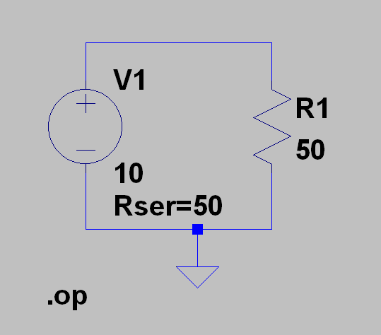 However, this gives you a basic feel for the four parts of LTSpice: the schematic capture, the models, the simulation engine, and the output. There’s plenty more to learn, but you can do some pretty interesting DC analysis with just the tools we’ve discussed. If you want to experiment, you can try simulating an LED and the effect of different dropping resistor values. Another classic Spice “experiment” is showing that maximum power transfer occurs when the source’s resistance equals the load resistance (see the schematic to the left). Next time, I’ll show you more about that schematic and AC circuits, too.


“created in 19XX”
1973, says Wikipedia
I could have swore I put that right before I posted. Thanks for pointing it out.
I though it was a Megaman reference
I usually have some salt, pepper, and Old Bay nearby. Plus parsley flakes, bouillon, and bacon bits for the ramen. :D
What is up with the video?
“If the owner of this video has granted you access, please sign in.”
I get “This video is private”
I get “Please sign in to view this video.”
Should be fixed now.
I talked to the guy who wrote LTSpice for Linear. He confirmed that it is designed and tested to run on WINE. So it’s not just a happy coincidence that this works, it’s by design.
I made sure to thank him for that :-)
Runs great on Wine!
I run great on Wine!
Kentucky Straight Bourbon Whiskey fuels me up. LOL
Does Spice would work as expected with the correct abbreviation for mega (“M”; https://en.wikipedia.org/wiki/Metric_prefix)?
At least when working in LTspice, the suffix “Meg” is used, as if you use “M” it is automatically converted to “m” which has caused me endless confusion.
That’s actually in the post. Use “meg” (no quotes) for mega. M is milli.
Ah, yes it is. I missed that last sentence about case-insensitivity.
To anyone who is a mac user and wants to get spice, there is also a mac version, however I’ve heard its not quite as good as the windows version. You can use a bootcamp partition or a virtual machine to make it work. I personally use winebottler so I can run wine and use that to run spice, and it seems to have no problems. If you are looking at using wine bottler, you need to go through the program files and pick the file called “scad3.exe”. Also, before you run a simulation make sure you create a folder for the simulation and save it there, if you don’t LTSpice will dump into your program files and its a mess.
As far as setting up the schematics and simulations, there is a help manual under the help tab, and it gives you basically anything and everything you need from syntax to interconnecting parts, everything is in that document. I hope all this can help the beginning hackers and the more hardware than software savvy.
Now I will accept my hate because I’m sure someone will rip my nuts off for the way I did this.
I’ve been using LTSpice for about 6 months on OSX and it’s been a huge help for analog development. The GUI is odd for the Mac incarnation but once you get used to using right click for almost everything it’s pretty easy to use.
It allows me to do things on my computer that would otherwise require an 8 channel scope and a bunch of tools I don’t own.
BTW: The video is marked private…
My issue with SPICE is that for any moderately complex circuit, simulation is (or just feels) unreasonable. I can make a resistor divider or an LED circuit in SPICE just as easily as I can sketch and solve it on a napkin, but if I’m making a buck regulator with parts not made by LT, pouring through the datasheet and trying to hack together a model seems like a waste of time. I suppose you could break everything into tiny parts and sim those but where is that line between “meticulously and cautiously design each part before fabbing a board” and “just get a prototype to the lab ASAP and we’ll iterate till it meets spec”?
Really depending on what you are simulating. Are you doing a full design simulation or testing part of the circuit?
What I usually do using your power supply example is to simulate the support parts other than the actual chip. If you can’t find or build a model, that’s about the only things you could do.
I can’t simulate the transient nor the stability, so that’s where the application notes comes in. The chip designers and the app engineers probably done their homework, so following the sample circuit should be fine for 90% of the cases. For the 10%, either you know your way or ask for their support.
The rest of the support circuits – sizing/alternatives, efficiency, losses etc are usually what I tend to customize anyways. Pick a LT part that is similar to what the other part is. i.e. similar switching frequency, similar topology and.build from there.
I have also make my own circuits out of comparators or discrete using whatever models I can get my hands on. Those have proved to be useful. I would rather sit in front of the computer running simulator than fooling around soldering and hacking circuits. I can try a dozen of things in the simulator and plot stuff that normally are hard to measure in the lab in an afternoon.
Making a mode is not easy as there are lot of experiences needed for these kind of work. This is something for a seasoned engineer with a lot more of the math and analog background. There are companies that make models by measuring the actual samples. They cost a lot of money as it is a lot of work.
BTW I went with the doing a full simulation instead of dicking around in the lab until thing works. I was the “newbie” while a “more experienced” guy with supposedly a few designs under his belt did the lab approach. My design passed the compliance test on first try and went to straight production while he spent an extra 3 month and needed another board spin.
YMMV, but I have consistently doing homework upfront instead of burning midnight oil debugging protos.
After factoring in the cost of labor and potentially expensive components, as well as the cost of lost time due to lag time for parts requisition, the cost of simulation is relatively small. Additionally, the re-usability of models means that even a hobbyist is likely to be able to amortize the cost of custom simulation models over multiple projects.
So use the other manufacturer’s SPICE model. If they don’t have one, I don’t use it.
The spice indicator for mega is X
For everone else fed up with bloated, windows only, and closed sourced software (or worse, emulating bloated windows closed software in WINE), I suggest trying QUCS http://qucs.sourceforge.net/
It has nearly all of the capabilities of ltspice (dc/ac/transient, s-parameter, noise, harmonic balance, etc), in addition to very nice integration with Octave or Matlab for advanced data processing and FreeHDL to allow fast simulation of digital circuits. You are also free to use it for applications other than “solely to evaluate LTC products”
Too much FUD.
LTSpice and help file is only 10MB and do not require silly frameworks or other dependencies, so it is hardly bloated.
They come with Linear Tech models, but you are free to use your own models and do not even need a single LT part to run a simulation.
While I love (and make) OpenSource software. You should not advertise it like this. It looks bad on all of us that love FOSS.
Don’t bad mouth other software. There is no reason. Just show what the other software does different/better. And also tell what it does NOT do to set proper expectations.
And Wine Is Not an Emulator. If LTspice is actually developed and tested to work on Wine isn’t no different then using any FOSS library.
Did not know about this option. Thanks.
I use QUCS here, it is worth sharing your knowledge if you have the time.
You could do a QUCS version of Al’s tutorials, to compliment them.
Thanks for the awesome article! several years back while doing my PhD research, I ended up writing a lot of text-based SPICE decks and ran them in WinSpice. I always enjoyed the card deck approach to the graphical approach especially when i needed to run a simulation 100,000 times with slightly different parameters, a single script could do that for me.
For Graphical SPICE programs LTSpice is a great tool. I still get a kick out of the SPICE acronym “Simulation Program With Integrated Circuit Emphasis”. Doesn’t seems like a lot of thought was put into it.
You can read a netlist into LTSpice and simulate it. Another trick is that viewing the “error log” actually just shows you the output if you have .MEASURE or other statements in there.
You can not only read netlst, but also change it, starting the simulation with new parameters, reading the result, and again changing the parameters. I did this with the Delphi program when I simulated the traction power supply system for an electrified railway.
“They didn’t fly into space, storm a beach or bring back the gold! No Sir, we did! It’s you and me against the world! I like your grit. Hustle could use some work though.”
-Cave Johnson
Such advertisement for LTSpice ! What about TINA from Texas Instruments ? Easier to work with, no such a deal to copy paste, more components already included etc etc…
Most hobbyists would be served fine with
http://www.falstad.com/circuit/circuitjs.html
That is fantastic in terms of it’s educational value, but how does it fit into a tool chain, e.g. output to KiCad for board layout? The Qucs KiCad combination is very complete.
I mentioned it too: http://hackaday.com/2015/07/20/a-breadboard-in-a-browser/ (including a little blurb about TINACloud). We’ve also talked about EasyEDA: http://hackaday.com/2015/08/21/a-tale-of-two-browser-pcb-tools/
Many choices.
It failed me a few times because the models were lacking. It might be good for beginners because it obscures the details (well, Spice too), but as you progress it becomes more of a hurdle than help. The power of Spice lies in the models.
I use ltspice as well. It is a great tool. Where I have a problem is with the models. Many perform differently than their real world equivalents. This can lead to the classic garbage in garbage out scenario. One example is a transistor with speed hfe of 150 but a model he of 500. Let has done an awesome job in providing this free tool to everyone but the manufacturers that make the parts have not done as well. Thanks for the tutorial. Knowledge is power.
Jim
Another thing that can affect simulation accuracy is that every instance of a model behaves exactly the same. A differential input stage will never have an offset in simulation, because all transistors are perfectly matched.
Then there is power handling. 100 Amps through a 1N4148? Spice won’t complain…
LTSpice is fun and easy to use, but if you are looking for scriptable, try out ngspice. I actually use it sort of like unittests on some of my more complex circuits, automatically testing across the tolerances of various components.
FYI: Tutorial for LTSpice
>Linear Technology’s LTSpice can handle both Monte Carlo analysis as well as worst-case analysis.
http://k6jca.blogspot.ca/2012/07/monte-carlo-and-worst-case-circuit.html
FYI: Yahoo forum for LTSpice (2002-2016) and mailing list info
https://groups.yahoo.com/neo/groups/LTspice/info
Sadly you have to join the group to view the messages. It is very active (Jan 2016 alone has 1099 message)