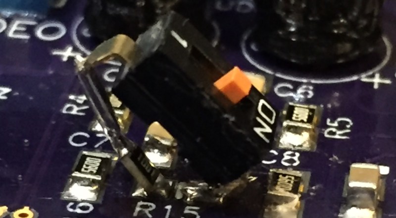
Making revisions to existing PCBs with surface mount components often leads to creative solutions, and this insertion of a switch over a tombstoned resistor is no exception. According to [kubatyszko], “this is an FPGA-based Amiga clone. R15 serves as joint-stereo mixing signal between channels to make it easier on headphone users (Amiga has 4 channels, 2 left and 2 right). Removing R15 makes the stereo 100% ‘original’ with fully independent channels. Didn’t want to make it permanent so I decided to put a switch.”
Whether [kubatyszko] intends it or not, this solution is not going to be permanent without some additional work to mechanically secure the switch. We’ve tried this sort of thing before and it sometimes results in the contact area of the resistor being ripped off the substrate and separated from the rest of the resistor, rendering it useless. However, the creative use of the pads to get some additional functionality out of the board deserves some kudos.
We love creative fixes for board problems but it’s been a really long time since we’ve seen several of them collected in one place. We’d love to hear your favorite tricks so let us know in the comments below.


I sometimes do this sort of thing when I don’t have the right SMD resistor at hand. When you need two resistors to get th desired value, you can just have them touch in the middle. Three means that you get to build a kind of SMD Stonehenge.
For more than that, it’s easiest to first solder rows of a few together on the back of some scrap FR4. You can use Kapton to hold them in place while soldering and to position them properly. This works best if you have a gap of about 6mil.
* Kapton for soldering and holding in position on the FR4
You’d need a lot more than three to make a proper ‘henge. Three would make a Trilithon. And at that scale, you couldn’t actually make the knobs go to eleven.
However they would fit through the stage door at Royal Albert Hall.
Ooooh… I’ve got an idea now for a resistorhenge potentiometer that allows the knobs to go to infinity! Watch for a Kickstarter!
what i need is the ordercode of the switch (is not a joke)
found recently some on ebay: http://www.ebay.com/itm/221813986090?_trksid=p2057872.m2749.l2649&ssPageName=STRK%3AMEBIDX%3AIT
Not the same colour and probably not a solid supplier like mouser or digikey.
Here’s a few items from my bag of tricks.
An alternative solution that’s less susceptible to mechanical stress is to use fine gauge wire wrap wire. I use 30AWG wire wrap when validating my prototypes or implementing fixes or minor design changes…makes connecting traces, component leads, or test pads to the scope or logic analyzer much easier, too.
Oh, and I’m very interested in reading more about this FPGA Amiga clone!
30AWG Kynar is the de-facto standard bodge wire, and the light blue variety is responsible for the alternate term “blue wire”.
However I’ve recently switched to using salvaged magnet wire where abrasion resistance isn’t a concern.
Love me some Kynar, back in the 1980s Red Kynar was popular for bodges, when I used to repair game consoles in this past decade I used Blue, and now I use Purple Kynar almost exclusively.
OK, I’m confused. Why in the world would you do it this way?
There’s plenty of board space beside them. Turn the resistor 90 degrees, soldering it to only 1 pad. Flatten both of the leads of the switch. Solder one switch lead to the switch, turning it at an angle so it doesn’t interfere with the resistor. Then solder a wire jumper between the other leg of the switch and the other end of the resistor.
Now both components have at least one leg soldered to a pad, and are flat on the board, and you can epoxy down the other leg of the switch so it’s not putting torque on a joint.
Why not use a potentiometer as a “stereo separation” control?
Maybe because it can’t go to “infinite”?
Infinite resistance? You mean “open”? Because there are *tons* of available potentiometers that have a built in switch — they’re everywhere.
Just hot glue it, it’ll be some secure
I just posted too about bodging and fixing pcbs on my website :) Must be in the air ;P However I don’t like the free hanging of the switch though, but does the job during testing I guess :)
http://smdprutser.nl/blog/fixing-late-night-pcb-design-errors-adding-pullups/ Post about swapping signals like MOSI/MISO will be soon too.
Solder down the switch, resistor onto a perfboard, connect it with wire AWG#30 wire and glue down the perfboard.onto empty area on the main board.
I’m so used to doing this stuff that I forgot that it is called hacking (and) deserves a feature on hackaday
Just seeing that picture makes me anxious, I’m just imagining someone sneezing and that switch pulling the pad up and breaking the resistor.
You’re not the only one.
why not do what 99% of everyone else does and put in some mod wires and glue it down? this setup will snap that resistor or even worse lift a pad
Hot glue and wirewrap wires are my friends too… I would have glued the switch down somewhere and connected a wire to the tombstoned resistor and pad. At least for something that needs to get switched a few times, this is much better than having a half broken resistor or solder joint that messes up your circuit without any visible clue. Finding these errors/failures can cost you a lot more time than doing these proto-fixes with a little bit more thought and care.