
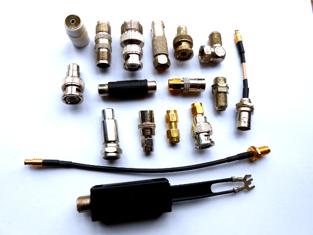
If you do any work with analogue signals at frequencies above the most basic audio, it’s probable that somewhere you’ll have a box of coax adaptors. You’ll need them, because the chances are your bench will feature instruments, devices, and modules with a bewildering variety of connectors. In making all these disparate devices talk to each other you probably have a guilty past: at some time you will have created an unholy monster of a coax interface by tying several adaptors together to achieve your desired combination of input and output connector. Don’t worry, your secret is safe with me.
There are a huge variety of factors that lie behind the choice of RF connector on a piece of equipment. You might imagine that the most important would be the physical and electrical specification of the connector itself, but other factors such as company design policy, the accepted norm of a particular field, and the personal preferences of the designer come into play. This article will look at some of the different types of connector and try to explain some of those choices.
Form Follows Function
Before looking at individual connectors it’s worth looking at the much broader picture, of what an RF connector does and why it is designed in a particular way. And for that we need to talk briefly about characteristic impedance without descending too far into the mathematical proofs that detain first-year electronic engineering students.
So, imagine an infinitely long piece of coax with RF flowing though it. If you were to non-invasively measure the RF voltage and current, you could then calculate an impedance in ohms in a similar way as you might a resistance in a DC circuit. In a perfect piece of theoretical coax this impedance figure will be the same no matter what the RF frequency or voltage is; it is dependent on the physical properties of the coax itself, the dimensions of the conductors and the dielectric properties of its non-conducting components.
If you connect anything to the coax in the previous paragraph, it must be designed to present the same impedance as the characteristic impedance of the coax. If a different impedance is presented then some of the RF will be reflected back down the coax, the total impedance of the system will be changed, and signal loss will occur. From the RF signal’s point of view then, anything you connect to it should look electrically like just more coax.
There in a nutshell is the problem faced by designers of RF connectors: to ensure that their product appears throughout all its parts as exactly the same impedance as the coax it is connecting. Electrically it must appear as though the connector is not there: an unbroken piece of coax at the desired frequency of operation.
To achieve this perfect impedance match the designer of an RF connector must ensure that the internal diameter of the outer shell, the diameter of the centre conductor, and the dielectric properties of the insulator are such that at all points during the signal path the characteristic impedance is the same. If you were to saw a typical high-performance RF connector in half lengthways then you would see it in action, great care has been taken to achieve this aim.
It’s worth mentioning though that sometimes this goal of constant impedance has not been pursued. Popular connectors have a habit of staying in use for many decades, so a few that you’ll encounter such as the Belling-Lee antenna socket on European TV sets or the now-inappropriately-named “UHF” you’ll see on HF radios are really old designs conceived before the mechanism of characteristic impedance was fully understood. Or in the case of the “RCA” phono connector, a similarly aged design whose roots lie in audio and whose RF properties were of no interest to its originators.
There are a myriad coax connector styles, both obsolete and still on the market. Some of them have very specific applications while others are intended for general-purpose use. Fortunately of that huge catalogue only a few styles have become popular enough that you might commonly encounter them, so when taking a look at individual connectors in detail we only need to consider a few examples.
Welcome to the Coax Connector Jungle
Starting with the oldest of our selection, the Belling-Lee has its roots in the 1920s. If you are an American you may never encounter this connector, because it survives only as the antenna connector on European and Australian TV sets. Thus you can buy set-top boxes and even RTL-SDR sticks with one fitted. It is used with 75 ohm cables for UHF TV, but it does not present a constant impedance to the cable. Probably the only reason you’d use one would be if you are working with very old equipment, a TV set, or a TV peripheral, so it is presented here largely for information.
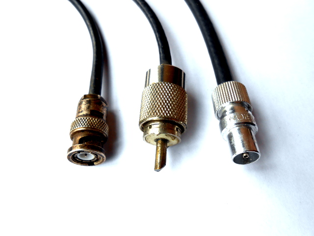
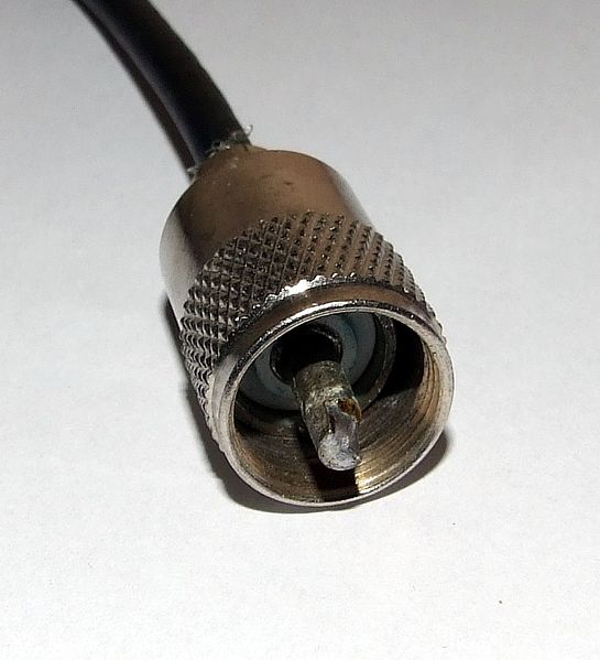
The UHF connector by comparison survives in a multitude of places, being used for video as well as with radio transmitters and receivers from HF into the VHF range. Dating from the 1930s, it takes the form of a shielded version of a banana plug with a threaded collar to provide a secure connection. It does not present a constant impedance, so is recommended for use only below 150MHz. “UHF” meant a somewhat lower frequency in the 1930s to what it does today. You’ll also see it referred to as a “PL259”, a wartime US military designation for one variant.
You’ll find the F connector in cable TV systems, satellite TV installations, and as the antenna connector on American TV sets. The F is probably one of the easiest connectors to fit, using the centre conductor of solid-core 75 ohm coax cable as its centre pin. It has surprisingly good performance for such a simple design, with a bandwidth of well over 1 GHz.
The BNC dates from the early 1950s, and has become ubiquitous everywhere from video systems through test equipment, handheld transmitters, Thinwire Ethernet, and many more applications. It is a constant impedance connector available in both 50 ohm and 75 ohm versions, and has a bandwidth somewhere around 5GHz.
SMA connectors were developed in the 1960s, have a 50 ohm constant impedance and a bandwidth of up to 18GHz. Being intended for use with semi-rigid coax on RF paths inside equipment they are not designed for more than 500 mating cycles. You will encounter them on some hand-held radios and most WiFi equipment, and they seem also to have become common on software defined radios. There is a variant of the SMA that you will also encounter, the Reverse SMA has its pin on the threaded side of the connector. This was an attempt by the manufacturers of WiFi equipment to stop end-users fitting Yagis and similar high-gain antennas, thus breaking radio emissions laws.
And finally, the MCX connector is a sub-miniature connector developed in the 1980s. They have a 6GHz bandwidth and are available in 50 ohm and 75 ohm variants. The MCX is included here because it is commonly used on RTL-SDR USB digital TV sticks, though if you own an RTL-SDR the chances are you use it with an adaptor to another connector series.
Choices, Choices
That’s the list of common coax connectors. Now which should you be using? Of course, as with any component choice, it depends on your application. But since few of us are working at the bleeding edge, it’s likely that none of our applications are going to be so demanding that any of a selection of the above couldn’t do the job. Thus there is another factor: personal preference. My personal preference will be different from yours: you may love the simplicity of an F while hating the soldered centre pin of a BNC, for example.
So here follows my preferences — what I reach for when I want a coax connector.
![A BNC plug. By Swift.Hg (Own work) [CC BY-SA 3.0], via Wikimedia Commons](https://hackaday.com/wp-content/uploads/2016/03/592px-bnc_connector_50_ohm_male.jpg)
![An SMA plug. By en:User:Meggar [GFDL or CC-BY-SA-3.0 ], via Wikimedia Commons](https://hackaday.com/wp-content/uploads/2016/03/sma_connector.jpg)
It’s important to note though that there is no wrong answer in this field. Open up an RSGB or ARRL VHF or UHF handbook from the 1950s and you’ll see a plethora of components and techniques that you’d be forgiven for looking at in amazement from 2016 that they ever worked at all. If there’s a lesson to be taken away from that it’s this: your radio is only as good as what you manage to do with it.


With everything getting smaller and smaller u should probably add U.FL to this list.
Or one of my new favorites, W.FL. Perfect for when a U.FL micro connector is too big! (paired with a 450ohm resistor, a W.FL makes a handy high speed oscilloscope probe that you can design into a PCB or solder down later.)
MHF4 is in there too: http://www.hwtools.net/Accessory/RF22xxxB.html
And SMB
The GR-874 deserves honorable mention on the count of being hermaphroditc.
http://proxy.w140.com/tekwiki/wiki/GR-874
Oooh! There are hermaphroditic RF connectors!?!? I love hermaphroditic connectors! I already switched most of my power connectors to Power Poles for that reason. Now I’m dreaming about switching all my RF connectors. Why? I love the idea of having a big drawer full of the most generic part possible that I can reach into whenever I need something. Otherwise.. when I need a female I’ll find I have a drawer full of males, no females and vice versa. I even use LM317s and fixed resistors when I need a fixed voltage… although.. I will probably be switching this practice to something involving a switching supply soon for efficiency reasons.
But.. since I never see equipment using these connectors… and nobody I know uses them… there is the downside of becoming incompatible with pretty much everything…
Decisions, decisions…
I have seen the General Radio 874 connector a couple of times in my career, on uber-accurate lab grade stuff, never on anything normal people use.
There are also hermaphroditic connectors on some expensive test-equipment (network analyzers). They have a threaded collar on each side, but you only use one of them and screw the other one back to expose the male thread. They are good for very high frequency (up to 40GHz or the like) and very expensive.
APC-2.92? (https://en.wikipedia.org/wiki/APC-7_connector) Very pretty. And yeah, they’re expensive, even the “cheaper” 3.5mm ones.
Page break please
Reverse SMA was actually MANDATED by FCC to prevent violation of Part 15, which requires a permanently attached integral antenna. That wasn’t always practical for wifi stuff, so FCC settled for a “unique connector”, the reverse-SMA…for which adapters to regular SMA “for testing purposes only” appeared almost immediately (and are now commonly available). :-)
Now there are cheap chinese handheld radios with reverse sma connectors and all the associated accesories one would expect to fit them. It just goes to show just how hopeless it is to make laws like that!
They are not reverse sma but male sma on the radio and female on the antenna. For some reason most ham radio companies are fixated on having a female sma on the radio which is a mistake. I would much rather have the wear end of the connector be on the cheaper antenna rather than the radio. One of Yaesu’s first handhelds with a sma connector was male on the radio. They switched to the female and stuck with it when they released the FT-50.
Yeah, I was about to say the same thing.
“They are nice and small, but not at all cheap (they are usually gold-plated, after all!), ”
There are *plenty* of non-gold plated SMAs. In fact, most of my high end SMA cables are *not* gold plated, because, well, the gold plating is more of a marketing thing than anything else, and gold plated connectors can tend to wear out faster than stronger platings.
“Being intended for use with semi-rigid coax on RF paths inside equipment they are not designed for more than 500 mating cycles. ”
Woah, woah. That 500 mating cycle limit is marketing-speak on just about *every* RF connector. N connectors are typically rated for 500 mating cycles, BNCs are often rated to only 500 mating cycles, etc. And that depends on quality of the connector, too: I’ve seen BNCs which were rated for only *50*. That doesn’t mean they’ll fail, it might just mean they didn’t test the design for more than that (for cost reasons).
It isn’t until you get to smaller connectors, like U.FL, W.FL, etc. that those ‘mating cycles’ are actually real, and then they’re more like *30*. In fact, finding RF connectors rated for guaranteed performance for *more* than 500 cycles is really very hard.
At the hobbyist level you’re probably right. But in the professional world we use 3.5mm over SMA for the reasons discussed in this .pdf: https://www.gore.com/MungoBlobs/671/522/Intermateability_Microwave%20Journal_Pino.pdf (basically, 3.5mm mates with SMA but has lower insertion loss and a 3000 mate/demate lifetime)
Here’s some “cheap” 3.5mm adapters on pasternack, one of the cheaper sites to buy RF things from: http://www.pasternack.com/nsearch.aspx?keywords=3.5mm Not a single thing seems to be under $100. Which to a corporate budget is nothing. At the hobbyist level though, I can see why you’d prefer N type and other connectors. Plus, who needs to go up to 26GHz?
Yeah, I wasn’t saying that SMA is awesome. I was just comparing it to the others listed here. ‘Hobbyist’ doesn’t make sense here, though. SMA, N, BNC, etc. are everywhere in the commercial industry. Most of my test equipment uses N, SMA, or BNC. It’s just a question of what the performance you need vs. the price you’re willing to pay. Maybe “commodity connector level”?
The 3.5mm connector is essentially just a “better SMA.” The measurements are tighter controlled, the dielectric is tighter controlled, etc. In fact, it was really designed as the connector that you can use to *test* SMAs with, which was an awesome choice by HP, because it’s a huge benefit to have a *higher performance* connector to test a lower performance one so you know where the fault is.
But, in fact, in my opinion, the existence of 3.5mm connectors is *why* SMA gets a bad rep for reliability, compared with N, BNC, etc. There isn’t really an equivalent for N, BNC, etc., and people know that there was a connector designed to be more reliable than SMA, so they think that N and BNC are somehow more reliable. They’re not. 500 cycles is pretty much the norm.
Pasternack is EXTREMELY overpriced. I’m sure there are companies who buy there, but not me. You can find everything on there somewhere else at a much lower cost…and not just junk from China either.
Someday, I will write a piece of fiction, and one of the characters in the story will be a Pastor Jack Pasternack…
B^)
Don’t forget to give his dog a bone.
In the professional (microwave) world we use just as many plain jane SMAs as 3.5mm. In fact a lot of people are out there right now mating regular SMA to 3.5mm and not even realizing it (Mwhahaha!) 2.9mm is even less often used. It’s just overkill unless you’re doing satcoms or crazy mm stuff.
The 500 insertions cycle is a majorly de-rated spec in any case. I’d use SMAs over anything else as they are secure, small, most of what I do isn’t taken apart that often to start with and I like using .141 simi when I can and not having to solder on a center pin is one last thing to deal with.
You forgot broadcast “connectors” — coaxial copper flanged pipe:
http://www.repeater-builder.com/antenna/images/hardline/6-inch-hardline-2.jpg
http://www.repeater-builder.com/antenna/images/hardline/6-inch-hardline-3.jpg
Now, THAT’s a connector :-)
That’s what those white slotted disks are! I’ve got a whole stack of them from a hamfest and now I know!
That zip tie must be a problem when trying to mate the connectors…
B^)
Dayum! Leaves the 7mm/16mm DIN in the dust, which until just now I had been thinking of as a large connector. :)
One other quick note on nomenclature. The BNC is actually an acronym for Bayoneted N Connector and is compatible and nearly interchangeable with the N connector.
Why, oh why, is it so hard to find correct information as to where the names of connectors come from? I’ve heard “bayoneted naval connector”, “bayoneted N connector,” but those are all wrong.
It’s “Bayonet Neill-Concelman”, after its inventors, Neill and Concelman. Neill *did* make the N connector (and Concelman invented the C connector), but it’s not “compatible” or “interchangable” with the N connector at all.
It *is* basically the same (with a different locking mechanism) as the TNC connector, because that connector is a threaded Neill-Concelman.
I probably should’ve said “why is it so easy to come across *incorrect* information as to where the names of the connectors come from?”
Even the Wiki page notes “A backronym has been mistakenly applied to it: British Naval Connector.[7] Another common incorrectly attributed origin is Berkeley Nucleonics Corporation.” To that we can add Bayoneted Naval Connector, Bayoneted N Connector, etc.”
It always makes me laugh when you hear people say “it’s not BNC connector, the C already stands for connector.” Which always makes me feel bad for Neill and Concelman – you invent something that becomes super-common, your name is on it, and then it becomes an acronym and everyone forgets it.
Yeah, I once saw in a Navy manual, that BNC stood for Baby Normal Connector!
B^)
” but it’s not “compatible” or “interchangeable” with the N connector at all.”
But a BNC will mate with a C connector!
Thanks for the April Fool!
Seriously, a BNC male will mate with a C female. They won’t latch, but the impedance will match.
You don’t want to know what “F” connector means :oP
“Field”-mountable? :-)
Incorrect.
“Bayonet Neill–Concelman”, the last two being names of engineers who invented the connector.
Not interchangeable, as the N connector has a higher your frequency limit (and an entirely different physical interconnect).
Then there was the time I was walking along downtown, and came upon a pile of garbage. Some computer boards, something to make me look further, and I find a drawer full of BNC connectors. I took only some, because I was going somewhere, but the pile was there on the way back, so I grabbed them all. Fairly heavy altogether, two or three hundred altogether when I counted them. Some new, but most were cut off cables.
And most of them were male.
So much for building everything with BNC connectors, I needed female for that. By then the local surplus place had run out of those bits of plastic with two female BNC and some other connector for 75cents.
Michael
BNC on coax used to be used for LAN networking (max 10mbit), so all those connectors where from an old obsolete network and the counter ones were on dozens of old ISA or PCI LAN boards I expect.
Yeah, it was called “ThinNet” cabling.
Gotta watch the impedance with found items like that, if they’d not packaged. Telling 50 ohm BNC from 75 is pretty easy; there is a lot less plastic visible in 75 ohm connectors.
Thanks, I was going to ask a question about how to tell them apart!
Nice thing is the 50 and 75-ohm versions of BNC can intermate both ways without mechanical damage. I dug this up when trying to decide whether to put up warning signs in the lab.
75 ohm bnc connectors have a larger pin and if connected to a 50 ohm jack will ream it out.
Note on the 50 and 75 ohm N connectors. The two series will screw together but not connect properly. A 75 male in a 50 female is a loose connection; a 50 male in a 75 female forces the female socket apart. If you are lucky you can repair in with needle-nosed pliers.
Thanks, good to know!
Not to mention that R-SMA appears to be the connector of choice for the sub $50 Chinese handi-talkies that have flooded the market. Good tip on the 500 matings. I hadn’t come across that one before and will warn my colleagues.
I haven’t seen any HTs with RP-SMA connectors on them, just male SMA. Which HTs are you talking about?
Practically every commodity RF connector has “mating cycles” ratings around 100-1000. SMA isn’t special at all.
So what happens after the max amount? I mean the screw threads or clamping would still work right? And the pin just goes in a sleeve, so the goldplating would get worn but it would still not be that serious surely, or would it?
I would think the effect is less than all those converters people have to use, which probably have bad matching and a lot of loss of signal.
And you can always clean the contacts occasionally.
And they make waterproof SMA and such, so you could avoid any serious oxidation even when the goldplating is worn down by using those.
Take a look at the design of most of the connectors listed here. They’re all basically “insert metal pin into metal sleeve-like thing,” with the sleeve slightly tapered/smaller than the pin so you get a compression fit (the pin pushes the sleeve open). Insert/remove the pin from the sleeve too much, and
1) the sleeve doesn’t compress enough to hold it tight enough for a solid connection
2) the pin gets pushed out of alignment enough that it doesn’t mate cleanly
In addition, the screw threads wear, so the alignment of the center pin gets worse as the threads get play.
The spec is derated. It’s based on statistical failures. And 500 insertion cycles is really a lot for most things you would use SMA with anyway, outside of handheld radios, and the other connectors they would use are no better. In fact the threads will last much longer on an SMA than the bayonet on a BNC, which by the way will allow the center pin to twist in its mate. an SMA when properly torqued will keep the center pin from turning. You’re going to make and break the connection A LOT before you ever reach 500 cycles, and even then it’s not a guarantee the connection will be degraded, let alone fail. It’s like SCUBA tanks. They can handle way more pressure than what they are rated to hold for a safety margin. We use a yoke valve which can only do 1500psi, but you can also use a DIN valve which will allow you to go to twice that pressure on the same tank (if it’s hydrostat is still good!)
It’s funny about those Belling-Lee connectors, they are indeed on TV’s in europe but the cable companies all use F connectors now, and then they you to downgrade for connecting to a TV or cable decoder, and it is pretty odd that they don’t simply put F type connectors on those.
Although it can be convenient that you don’t need to unscrew those Belling-Lee ones to unplug them, there’s something to be said for such convenience with connectors that invariable are at the rear of equipment and often in a group of other connectors, making access worse.
But hey, it’s also funny to see a HaD author write a long article about the stupid old stuff and then ending the whole exposé with announcing her favorite/go-to connectors are the most awful choices of the bunch.. pfff
Do they have similar specs though? Because I would think there is a reason why such connectors (as well as professional connectors) have a screw connection, and I don’t think it’s simply a fear they will get pulled out.
Mind you, MCX is push/pull too and they are DC to 6GHz.
N to F adapters..
Useful, cheap and I feel so, so very dirty when using them..
Where is the love for the F connector? Easy to use and make and cheap as long as you are happy with 75 ohms. Use them on my SDR connections, have seen them used successfully for 21cm radio astronomy set up using SDR dongles.
Never been a terrible fan of F connectors, they aren’t terribly durable compared to mostother things.
That being said, I have buckets and buckets of them around from my dads work as a television network builder. (this was in the 70’s or so)
Why should be love for the F connector? The sloppy installation of them leads to RF leakage creating inference issues for Amateur radio, CATV (in the US), land mobile radio, and sometimes for aircraft communications.
One thing of note is that the recommendations aren’t exactly hard limits, either.
A PL-259 can be used for most 144- 440 amateur radio rigs with no problems what so ever (Any higher than that though, you should be looking into N connectors.)
UHF connectors are shielded banana plugs? I’ll be darned… Learn something new every day, I guess.
Great article, please keep ’em coming!
It’s worth noting that of the lot the N connector is the only really weatherproof one…
Or you can use self-vulcanising rubber tape, when applied properly, it’s actually watertight ;-)
True, but N connectors are waterproof whether they’re mated or not.
DC Pin connector (or DC plug, for one common type of connector) is an electrical connector for supplying direct current (DC) power, DC connectors have many more standard types that are not interchangeable. The dimensions and arrangement of DC connectors can be chosen to prevent accidental interconnection of incompatible sources and loads.
Managing RadioShacks for years, and the best were the people that would come in and buy the RCA female to F adapter male because they didn’t want to spend $25 on the RF converter that they needed to hook up their kids PlayStation to an old tube TV… They never listened….
A ‘UHF’ connector. That’s where I stopped reading. It’s a PL259.
What it’s called is sometimes an indicator of your age.
While it’s nice to read about frequency range – how do these connectors handle water ingress?
Most antennas experience rain, and not everyone wraps connectors in insulating tape.
So….
What kind of connector is on the back of my smart tv?