Someone brought a dead Marantz amplifier to [Lansing]’s attention, a rather nice model from the 1980s with one channel entirely dead and the other very quiet. His account of its repair is straightforward, but provides some insights should you find yourself with a similar item on your bench.
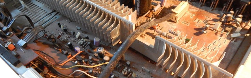
Opening up the box, he was presented with 35 years of accumulated dust. It’s the annoying side of cracking open classic kit, we all have our dusty horror stories. His first task was routine: to replace all the unit’s capacitors. The mains voltage in France has gone up by 10 volts from 220V to 230V as part of EU harmonization in the years since the amp was built, so he used capacitors with an appropriately higher rating to compensate. We might have waited until the rest of the amp was proven fixed before splashing the cash on caps, but maybe we’re more thrifty.
The quiet channel fix turned out to be from a muting circuit designed to keep the amp quiet during the turn-on phase and suppress that annoying “thump”. A dead transistor replaced, and all was well. The dead channel though had a whole slew of dead transistors in it, which turned the problem from one of repair to one of transistor equivalence. Quite a few of the 1980s parts were no longer available, so modern replacements had to be found.
It is tempting to think of particularly all small-signal transistors as functionally equivalent. You will get away with this in logic and switching circuits in which the device is either On or Off and never in between, but in an audio amplifier like the Marantz things are not so simple. A lot of effort will have been made by the designers to calculate resistances for the current passing through them to deliver the right DC bias points without sending the circuit into wild oscillation. An important part of that calculation comes from the current gain of the transistors involved. [Lansing] had to carefully select his transistors for equivalence, though it some cases he had to do a bit of creative lead-bending to fit a different pin-out.
So, all dead transistors replaced with appropriate equivalents, and the amp was reborn. Success, and very much worth the effort!
We’ve covered a lot of amplifiers here in the past. Some were dead, like this little amp with blown capacitors or this smokin’ subwoofer. Others are more esoteric, like this ion wind 1KV tube creation.


quiet channel was fixed be raplacing a cap not a transistor…
old ≠ classic
This is a Philips-era unit, most definitely not a classic.
If it was produced in 1980, it would have been designed before the Philips purchase. Unless Philips brought the design with them.
Marantz (IIRC) had an ad in stereo magazines during the 1970’s about a receiver that had been in an apartment fire, left in the wet debris for months and then thrown off the back of the dump truck ready to haul the debris away to the ground when the owner asked for it. He replaced the line cord and it worked!
Did you leave out the punch line of the story? The cord started the fire?
Sounds familiar…
http://i.imgur.com/oxwXVzr.jpg
I built a stereo amp from a kit not too long ago. I had a nice pair of patio speakers and an A2DP to line-level gizmo and needed to bridge the gap.
It wound up working, but I put one of the power supply rectifier caps in backwards and it promptly smoked. Halted had an equivalent part in capacitance, voltage and diameter, and that was close enough to score.
halted = hsc electronics
you are a bay area person. now we know ;)
http://alltransistors.com/ has an equivalent device search function.
Some things worth mentioning –
http://geh-tech.com/wordpress/wp-content/uploads/2016/05/SCH2.jpg
Most amp from this era have a current mirror at the beginning (Q702, Q704). It compares the input with the output and generates a difference voltage that drive the rest of the amp.
When you have a fault condition then most of the transistors (and related voltages) will be hard on, or completely off, so it’s useless to look for an “anomaly” because the whole channel is an anomaly.
Often there are several blown transistors and replacing *some* of the blown ones will just blow them again when you power it up because other the others that are still blown.
Here is a generic way to repair them without having a circuit diagram or being very experienced.
For the faulty channel –
Check the two larger output transistors on the heat sync for shorts. These are the most expensive transistors so re-use them if they are ok.
Check the third transistor on the heat sync for shorts and re-use it if it is ok. This one is not that expensive but it is often involved with setting the quiescent current temperature compensation and it’s better to avoid having to re-adjust that.
All the smaller transistors will likely be cheap so just replace all of them, change all the caps if they look old or test them with an ESR meter. re-solder the dry joints as well.
The transistors will be to-92 and there are two pinouts so get the right substitutes if the originals are not available. Match substitutes by pinout, NPN/PNP, Bipolar/Darlington, Hfe, Vce. You need at least the same Vce or the full power supply rail to rail swing with a extra bit for error, Hfe can be a little higher but not too far or it will oscillate into smoke. A darlington transistor is a dual transistor in one package and usually have a very high gain (Hfe) of around 1000 or more.
You can test the transistors with a meter looking for shorts or open circuit junctions and this is even easier if one channel is working but you have to get every dead one or smoke again. I a transistor is part of a current mirror or totem pole then replace it’s complementary transistor if you are substituting.
How to power up.
Replace power supply fuses with small one like 500mA. power up with no signal and check dc-voltage on speaker connectors. It will be very low or you still have a problem. If no problem yet then connect some cheap low power test speakers and play some really low volume sound just to see that it sounds ok.
How to set the quiescent current (if there is a pot on in the amp). Do this if you had to change the third resistor on the heat sink or want to be thorough. Disconnect the other channel. Get some fuses and pull them apart and remove the fuse wire and replace it with 2.2 ohm resistors. Put them in the fuse sockets. Power up with no signal (short the input). The voltage across the resistor/fuses should be close to the same. If not start over you have a problem.
Use A = V / R to calculate the quiescent current with no input (input shorted). It should be 50 – 150mA, The schematic has this but 75mA – 100mA per channel is ball park. Adjust the pot to change it. If it is too high then the output stage will overheat even when there is no signal. If it is too low then you will get a zero-crossover distortion even at low volumes.
If the current is jumping around when your adjusting then try some oil on the pot or replace it. Set the replacement 25% from the minimum current end before power up.
Once it’s fixed – These old amps have no fans. Give them plenty of space to breath (thermal convection).
Safety note: The fuses mentioned here are the fuses on the DC side of the power supply and definitely NOT the fuse (or fuses) in the mains voltage side. Generally there is ONE fuse in the main / high voltage side and the amps often have two fuses (positive and negative supply rails) on the DC side or even two fuses per channel.
If you can’t tell which is the mains voltage side and which is the secondary side then don’t open it. Like any main voltage appliance you need to understand the safety implications before venturing into a potentially fatal repair.
Thanks RÖB,
Yes, there was only a fuse on the primary side. it blows when I started to trim the quiescent current with the pot on the wrong side (max current…). For information, the fuse was a 1.5A Slow acting.
Sounds like good advice, RÖB. One nit-pick: it’s not a current mirror, it’s a differential amplifier.
Thanks for the correction. I was trying to remember what that configuration is called and I kept thinking “long tail pair”. Although I did repair an amp about 6 months ago (for a friend), it was the only amp repair I have done for a number of decades. My memory isn’t that good now lol.
Can I be the first to request that RÖB be hired to write some articles on repairs like this?
I’m a software/embedded guy, my analogue skills are low and rusty and I’ve got two old amps in need of repair, I know I have the kit to do it (soldering iron, scope, dmm, power supply) but I’m very wary of even powering stuff up in case it explodes. I’d love an expansion of RÖB’s post above going through the various stages, generic layout/operation, fault finding, component substitution, etc. as it seems like a bit of a lost art.
+1 good comments on tube amps I think I asked him to elaborate a comment a while back but it was lost in the comment heap
Electrolytic capacitors dry out, so just replacing the whole lot straight off is sensible. As to the power supply caps, I’d be more concerned about the mains transformer being “over-volted”. But given that it is a 50Hz transformer, not an American 60Hz design, I would trust in design margins and today’s better mains regulation to handle the difference.
Regarding transistor replacements: I designed high power (150W was a lot in those days!) amplifiers for rock groups in 1968. The transistors I used then are pretty much the same “standard” ones as today – the characteristics of run of the mill discrete transistors have not evolved very much at all. As long as it was a silicon design and not germanium (in 1980 it would be all silicon), I’d simply substitute transistors for their position in the circuit; low noise for the magnetic pickup input stage, medium power and of course high power. In fact, the only ones I’d put some serious study into would be the output and driver stages, where Hfe vs current could be important.
There’s also the aspect of maximum thermal dissipation and peak current capability, the newer transistors tend to have smaller chips and that greatly affects this.
Most of these one big ckt board design amps (not classic) fail at solder joints. The ones going to big transistors are first in line to go. Second are the hot running things left, >half watt resistors and TO220 power regulators. They fall like a house of cards when one big current excursion happens.
No… MOST of these one big ckt board design amps fail because the owner unwittingly shorted the speaker output.
B^)
I am saving this comment thread to my HDD for the day my A400 packs up. Thanks guys.
I’m pretty sure the voltage didn’t go up in France… (it didn’t go down in the UK as it was too expensive to replace equipment and there was little to no benefit.)
harmonization was about setting standards for equipment. so equipment needs to be able to work at 230v +/- 10%
that allows UK 240v equipmnt to work in continental Europe on a 220v supply (-9.6%), and allows French 220v equipment to work at UK 240v levels. (+9%)
it used to be that the “standard for electricity was +/- 6%, harmonization just widened the tolerances.
Hello, the voltage increases from 220V to 230V between ~1990 to 1996. In absolute, you’re right it doesn’t change a lot. By theory, the secondary increase from about 2V. In this amplifier, I measured a little bit more.
Bye
Came here to.post this.
But I thought it was 220V -6%/+10%
Sorry 230V not 220V
This is also why Chinese crap works fine in Europe