It is likely that many of us will at some time have experimented with motion detectors. Our Arduinos, Raspberry Pis, Beaglebones or whatever will have been hooked up to ultrasonic or PIR boards which will have been queried for their view of what is in front of them.
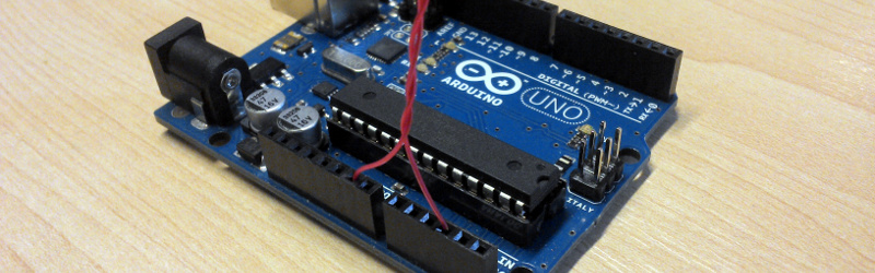
[Connornishijima] has stumbled on a different way to detect motion with an Arduino, he’s polling an ADC pin with a simple length of twisted pair hooked up to it and earth, and reliably generating readings indicating when he (or his cat) is in its vicinity. He’s calling the effect “Capacitive turbulence”, and he’s open to suggestions as to its mechanism. He can only make it work on the Arduino, other boards with ADCs don’t cut it.
Frequent Hackaday featuree [Mitxela] may have also discovered something similar, and we’ve hesitated to write about it because we didn’t understand it, but now it’s becoming unavoidable.
It’s always dangerous in these situations to confidently state your opinion as “It must be…” without experimental investigation of your own. Those of us who initially scoffed at the idea of the Raspberry Pi 2 being light sensitive and later had to eat their words have particular cause to remember this. But this is an interesting effect that bears understanding. We would guess that the Arduino’s fairly high input impedance might make it sensitive to mains hum, if you did the same thing to an audio amplifier with a phono input you might well hear significant hum in the speaker as your hand approached the wire. It would be interesting to try the experiment at an off-grid cabin in the woods, in the absence of mains hum.
If you’d like to give his experiment a try, he’s posted his sketch on Pastebin. And he’s put up the video below the break demonstrating the effect in action, complete with cats.
We like to see people pushing the boundaries of what is possible with their microcontroller I/O lines, it furthers our collective knowledge as a community. We’ve seen people making TV transmitters from ESP8266s, and not so long ago a Raspberry Pi ADC port as further examples. Please, keep them coming!


Here’s how it works:
There’s a capacitor between the “antenna” and the guy C1 and the guy and say the power lines(ground), C2. Let’s say it is uni dimensional. Let’s assume the power line/ground is at zero potential.
The sum of these capacitances is constant. C=C1+C2. But as he moves, the capacitors change so that C=C1′ + C2′, but the charge on the electrodes doesn’t change instantly. Since Q=C*U, if Q stays constant and C changes, U has to change. This is why the potential at the input of the ADC changes.
Of course, some leakage occurs bringing the thing back to some equilibrium U=constant, which is why the thing is sensitive to variations, aka the speed, not the position.
The twisted pair wires improve things because they can eliminate the common mode coupling to the mains line.
There are a a lot of differences in the ADCs of different boards/micros, but I have noticed the same phenomenon while working on my project which uses a capacitive sensor with a different board and micro http://www.electrobob.com/sit-up/
Nice work! Thanks for sharing.
So as a test, he can try his board in an environment free of AC voltages, yes?
So he could take the board outside in a park and try it, or out into the woods and try it using a laptop on battery power.
Scientific explanations should have falsifiable predictions.
For everyone who provides a guess, please remember to make some predictions about your guess – especially ones which would disprove your theory.
nope, the AC does not matter. As a matter of fact, the explanation is even simpler than I initially considered:
there is a capacitor formed between him and the antenna. The capacitance is dependent on distance. Since both him and the antenna are isolated*, you can say the charges they have are constant. As Q=C*U, by changing the distance you change the C, so U has to change, which is why it is read by the ADC.
*They are not perfectly isolated, there is some leakage resistance. This and the formed capacitance make a high pass filter, which is why it is sensitive to variations, not absolute values.
Will try to think of a falsifying way, cannot think of a method now other than tying him to the ADC input.
Actually there are a lot of high school physics problems which involve capacitors with moving plates*.
http://physics.stackexchange.com/questions/54649/what-happens-to-capacitor-s-charge-when-the-plates-are-moved-further-apart
*Your experience might differ depending on where you studied.
I think we used to do this “digitally” with a plain cmos input and a wire in High School. Using a 10Meg resistor and some diodes to protect the input, just put a piece of wire or maybe some aluminum foil. You’d get a change enough to trigger a one shot or something when somebody walked by.
You’re detecting The Force in living bodies. Obi-Wan had an arduino in his pocket when he uttered those famous words: ‘I felt a great disturbance in the Force’. I like the reaction on the graph from the cat. The force is strong with this one!
Plausible. That also explains floating input syndrome. The Force can have a strong influence on the weak-minded.
Because everyone loves cats and star wars!
List out your favorite things, because chances are it cures cancer!
I simply remember my favorite things, then I don’t feel so bad. But I doubt it could actually cure cancer.
laughed, i did
+1. Humour has intrinsic value, when, like capacitive turbulence, it catches our personages, offguard.
Wow, didn’t know my video was here until YouTube comments rolled in! Thanks HaD! Yes, The Force in strong in that cat, she can manipulate you even without words.
The theories provided about electrostatic charge coupling seem to hold up, I can rub a beanie on my head for a few moments put it on a long plastic stick (with the windows closed to hide my insanity) and the charged hat will also bring the readings up. This also explains why it’s more sensitive to hairy cats than myself. I’ve also successfully done this outdoors away from AC interference, though to run the project successfully I had to tie one of the GND pins to a grounding rod to keep the signal clean. So as a tip for anyone wanting better readings – ground the circuit as well as possible!
Hmmm so with a metal pole, an ATtiny, a wire, a solar panel/charger/battery combo, and a 100MHz crystal I could create a remote detector thingy for my garden. that would beep my on the FM band with a Morse code if it detected anything over a threshold.
Two years later and has there been any other updates? I noticed this same phenomena in 2014ish, about the same time everyone else apparently. I haven’t stopped playing.
https://photos.app.goo.gl/APLKRKZCyj9vD1j19
https://photos.app.goo.gl/anhcnP6knLd8zkzc6
Here’s a guess: It’s not capacitive coupling, it’s electrostatic charge coupling.
His body has picked up a static charge. When he moves closer or further from the wires, the charge in his body causes a movement of the charge in the wires. The AtoD has an extemely high input impedance, so it can measure these changes in charge as change in voltage. This affects both wires the same, but the charge on the grounded wire escapes into the ground.
If this explanation is correct, it should work without the ground wire – just a single antenna wire should do it.
If this explanation is correct, there will be less of an effect during humid days, and a greater effect in dry days (especially winter). On humid days the air charge quickly bleeds off – this is why static is a problem in winter but not summer.
If this explanation is correct, it should be dependent on the input impedance of the micro. High impedance JFET inputs will show this effect, while lower impedance AToD’s on other types of chip might not.
Also, the input capacitance of the chip and board play a part. If the wires on the board and the AtoD input capacitance is large, there will be less voltage generated for a specific charge. If capacitance is small, a higher voltage will be seen.
So different configurations of board – board material, trace width, effect of ground plane – should affect this.
The AtoD has a high input impedance/low capacitabce, but reading the AtoD should use up some of the charge on the wire. By my calculations the AtoD on an Arduino maxes out at about 400,000 samples a second.
If my explanation is correct, the signal should dissipate more slowly when the AtoD is read slower, assuming a low humidity day.
Some thoughts and experiments to try.
I vote for electrostatic too… there’s carpet, lot’s of textiles and the graph got nuts when the cats came… fur… electrostatic… you guess what I mean…
which explains the ‘foot’ reaction too: it is his sock, not the leg, that activates.
Moving charges causes the potential to change because the capacitance changes, like i explained above.
The ground wire has an advantage: it reduces the coupling of the 50/60Hz signal which i bet is larger compared to the signal from the motion. It provides common mode rejection.
Leon Theremin, anyone? That sure looks like an antenna to me….it’s the detector part, of course, not the rest of the instrument, which would make it a capacitance thing.
This might be fun to play with, I’ve got a couple arduino boards laying around here somewhere.
A long time ago I worked with a high pressure liquid chromatograph that had a electrochemical detector https://www.myantec.com/support/tutorials/electrochemical-detection that would deflect the chart pen* when I walked by or waved my hand at it. I was looking at 10-15 picoamp signals on the instrument that were above noise..
I ended up building a faraday cage around it which made it much more stable. I’m guessing the foot or so of ss tubing that formed the connections in the system served the same purpose as the twisted pair here.
*Yes, THAT long ago, output was a chart recorder, and yes I’ve integrated peaks by cutting out the traces and weighing them.
What are you working on now? I could use some help… I have had this tab open for a month now and want to do something fun (x-ray microprobe spectroscopy, voltammetry/amperometry): http://www.ti.com/product/LMP7721/description
I’m working on web applications, system administration and general IT stuff now, I stopped being a biochemist a long time ago. Sadly I can’t even remember what I was working that required the EC detector.
What do you want to do?
I can do analog as I am an old fart.
All I can tell from the link is that you really don’t like bias offset.
The theremin is sensitive to distance, not motion. I think that was the challenge here.
Yeah, but the principle is the same, I suspect, just a different application. Motion IS varying distance.
Motion is the derivative of position, something that senses motion senses speed, not distance.
Is this similar to this?
https://www.disneyresearch.com/project/botanicus-interacticus-interactive-plant-technology/
It seems that this was done two years ago in a much more useful project, http://www.instructables.com/id/Donut-Protection-Device-Advanced-Arduino-Technique/
Excellent, i have a use for this.
That is pretty damn funny.
http://cdn.instructables.com/FDW/D3ES/HTS5A6LS/FDWD3ESHTS5A6LS.LARGE.jpg
Hmmm, inductive antenna plugged into a high impedance input ADC.
It’s background noise absorption.
What’s the background noise ???, Static buildup on the carpet, mains hum, terrestrial transmission, local WiFi??? Who knows!
If it were mains hum then the Arduino could measure it’s period to confirm.
Would be handy to use one of the Arduin-o-scope programs you can get to see what’s in there.
I used this concept to get a pseudorandom number earlier. Just plug one wire into an ADC pin. Useful for simple stuff.
Careful there. There were known attacks against encryption based exactly on the the assumption that the mains hum disturbed the random generator inducing a 50/60Hz periodicity in it. If it’s just randomness for whatever purpose it should be fine, but if it’s a cryptographic random generator, the quality of the randomness is critical and an open input definitely isn’t good enough…
Well he did say ‘simple stuff’.
But very good point to bring up!
I agree that it is not good for crypto. But is likely better than some simple algebraic attempts.
Now the arduino theramin is cheaper than ever!
Hehe, funny I did stumble upon that too, although at the time was more interested in getting it to talk Midi protocol than having nasty “noise” every time my fingers went over a couple of wires coming from a couple transistor/capacitor pairs, and this was on the digital pins, not on AD may I add, but the capacitive turbulence description matches the effect like the a custom glove made to tight fit!
In the ancient times, when TV’s were analog during summer vacation we would put ourselves into strange statues just to watch soccer far out in the countryside!
And nobody should lose their stance!
Hahaha. My neighbor could get HBO when he sat on the TV way back when. Watched 10 minutes of Face Off before he gave up.
Anyone who’s interested in this should also take a look at the CapacitativeSensor library for Arduino. It works on the same principle, but it measures signal delay rather than voltage, so you can use digital pins instead of an ADC. The downside is that it requires anywhere from 1-10 MOhms worth of resistors, but most HAD readers probably have that in a bin somewhere.
Also you can have many sensors running at once! I believe it takes one receive pin per sensor, but only one send pin for the whole setup. Or was it the other way around?
I just got a bunch of ideas because of you.
Very interesting! Would love to use this in a project somehow.
At the risk of plugging specific hardware I would point out that the Cypress PSOC chips explicitly support capacative sensing which makes capacative touch controls and proximity sensing easy. They have a prototyping kit for their 4200 chip at $4 which includes a detachable serial to usb interface! Their IDE also seems pretty good. For example, you can do a lot with drag and drop. I have just started using this hardware and am so far quite impressed.
I don’t mind giving them a plug, they’re a good chip.
The ones mentioned above with the snap off USB-Serial bridge are $4 here –
http://www.cypress.com/documentation/development-kitsboards/psoc-4-cy8ckit-049-4xxx-prototyping-kits
I prefer the more advanced chip which has a snap off USB to JTAG/Debug section that can be used to program any of the PSoC chips. $10 here –
http://www.cypress.com/documentation/development-kitsboards/cy8ckit-043-psoc-4-m-series-prototyping-kit
I tried this out using four inches of wire and a battery powered Arduino and it works to detect a human within a few feet. First details of my trial can be found in the project “Little Friend” at https://hackaday.io/project/10162-little-friend/log/38612-human-detector-using-arduino-and-bit-of-wire
This is pretty cool and probably usable for a number of detection projects–however it actually works.
LOL this is not new for certain security
This needs taking out into the woods or something, you can’t test this in a home where electrical waves are everywhere.
Comments were TL;DR all. So this reminds me on Project Soli. If u would increase the accuracy that might work as well for gesture detection.
I didn’t read all the comment, but as I tried and played a bit with your code I printed out every 1mS the raw value of analogRead. But as mant though, putting values in an excel sheet shows a pretty distorted sinus @ mains frequency. Once passed in the averaging function, value stays steady around 700, You see variations when something is moving around the antenna. Pretty cool motion detector actually! Thanks for sharing.
Thanks for posting this – rather interesting. The “why” seems to be well diagnosed by others herein. What intrigued me is applications for omnidirectional motion detection instead of a PIR which IS directional. Also, it has mass discrimination so small creatures, such as mice, won’t be detected. I can see use of this in some unique applications where omnidirectional motion detection would be useful. It would also be inexpensive – I just purchased an UNO from AliExpress for $4.85 including shipping. EBay sells Arduino MINIs for under $2 delivered. This makes a DIY omnidirectional motion detection sensor cheaper than a PIR.
Glad you like the concept! It’s still very bare at the moment as I’m working on setting it up, but you can follow the hackaday.io page for this effect and my motion detection trials and errors!
https://hackaday.io/project/11982-arduinos-built-in-motion-detector
https://en.wikipedia.org/wiki/Volt-ampere_reactive#Physical_significance_of_reactive_power
Look for that reactive electricity and copper winding (the twisted pair is one of this copper winding) and think about which kind of energy is present all the times inside your houses and rooms….could you use this kind of energy to manipulate your body or mind? think about the sensor and how it read the energy around it, ground is a key….think about the sensor in the reverse way ? perhaps the hat in Connors head would be a hint…… ^^^.
perhaps this guy is not wrong….
http://www.theunticket.com/wp-content/uploads/2010/11/conspiracy_theorist.jpg