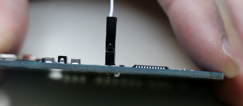
Like the fictitious invention of the Hula Hoop in Hudsucker Proxy, [David Spinden]’s big idea is small and obvious once you’ve seen it. And we’re not saying that’s a bad thing at all. What he’s done is to make a new kind of prototyping connector; one that hooks into a through-plated hole like a pogo pin, but in the horizontal direction.
 This means that your test-points can do double duty as header connectors, when you need to make something more permanent, or vice-versa. That’s a lot of flexibility for a little wire, and it takes one more (mildly annoying) step out of prototyping — populating headers.
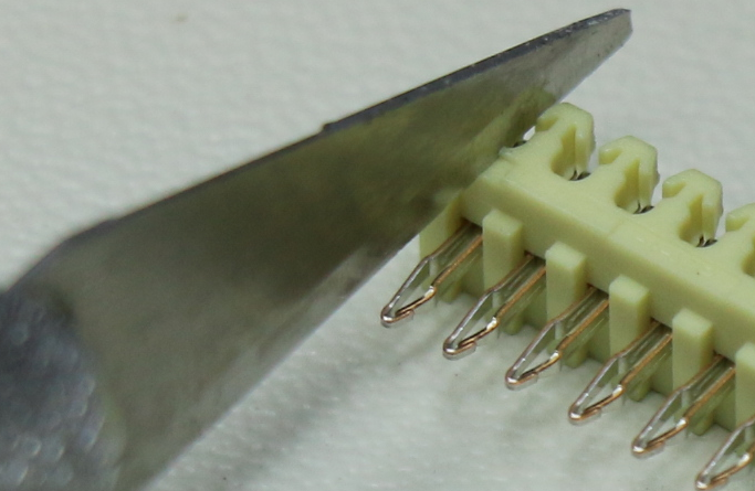
[David] makes them out of readily available header pins that already have the desired spring-like profile, and simply cuts them out and connects them to a standard Dupont-style hookup wire. Great stuff.
When we opened up the “Anything Goes” category for the Hackaday Prize, we meant it. We’re excited to see people entering large and small ideas that improve the world, even if it’s just the world of hackers.


Well, as someone that has a few hundred dupant mm/mf/ff connectors on my desk right now, I like it.
I’m assuming the boards these will work with are double-sided, only, because the hole’s inner “walls” are a small metal tube, right? Or is it making contact with the copper contacts on the top or bottom planes?
As someone that has a few hundred feet of small shrink tube on my bench, I’m using that. I find the DuPont covers a pain to use as singles. If I’m doing a multiple like 2*3 it makes sense, but one wire isn’t worth it. Nice tip, thanks for sharing.
Dear Mark,
Thanks for the interest. Good question. It would be nice to grab the top or bottom of the via platting for the greatest flexibility in use. That said, ViaConnect does require either plated vias (inner walls have copper like you said) or you can use rivots if you make your own boards. It grabs the copper inside the barrel of the vias.
Thanks,
David
I had been looking for something like this for a while, but was unable to find the springy connectors that he is using.
It looks like it needs a plated via to make a solid connection. I guess it might be possible to have a “test clip” in the format of a pair of J-shaped hooks overlapping each other that is small enough to fit through the via, but that naturally separates as it is extruded from its housing into an umbrella shape that connects with the pad around the hole. Removing it would require tweezers or similar, though, unless it were possible to make a profile that reverts to essentially a loop if pushed out far enough, allowing it to be pulled back through the hole.
I don’t think I’m describing it very well, unfortunately. And it is probably too complex to be reliable, or sustain multiple connections.
Perhaps a simpler idea would be to combine the spring action of these pins as a mechanism to hold the connector in place, with a springy connector around it to contact the pad
Won’t someone think of the children?!?!?! Just kidding this guy did, nice idea could you nextly incorporate current limiting resistors and maybe diodes to keep mistakes from being board lethal?
I am not a literal child but this still could be useful for people new to the art.
I think it it great. I always have to get a extra board to play with and try out my connections and this looks great.
Ans as he said It is great for the school learning environment.
I know I will be getting some on my next order. and make some up. Cant wait to buy them.
I realy hope it takes off. Good luck.
I can’t imagine an edit button for HaD, but I would love a preview button. Sometimes links are wonky, and I don’t know the proper way to link YouTube without it blasting the page yet.
Is there a sandbox somewhere?
Save that extra step and make cables directly. Those are insulation displacement connectors and you can just “push” in the right sized wire in with a screw driver. You can cut those “DuPont” cable in halves if you need the other end for headers.
It is a great idea, a company called interplex makes something similar designed for solderless connecting of boards. I got samples a while back thinking they’d be useful for something but haven’t used them. They call them solderless press-fit pins.
http://www.interplex.com/sunbelt/solderless-pressfit-for-automotive
http://www.interplex.com/interplex.nsf/c174f480052a6d3e85257e650068b479/bc9521441516452185257e73004d2b3d/Body_2/0.2FBA?OpenElement&FieldElemFormat=gif
Here’s another one that I like:
http://modtronix.com/hdr1x2pf-m254-p30.html
I wish they had something like these in a female socket header. It would be great for the pi zero.
Thanks Alex and CaptMcAllister for the suggestions. I am always impressed with the feedback on HaD.
I believe that press-fit pins dig into the via walls/barrels and are difficult to remove. One of the goals of the ViaConnect was to have little or no damage to the via. Press-fit connections are also designed to be permanent, another disadvantage for my project. I could be wrong on both accounts.
I invite any thoughts or corrections.
Thanks again,
David
Thanks for the suggestion Annie.
When I was looking for contacts for the ViaConnect, I searched Mil-Max’s catalog, but did not find anything with a horizontal spring contacts that I was looking for. If I missed something, please let me know. I did order one of these intending to hack it:
https://www.digikey.com/product-detail/en/mill-max-manufacturing-corp/803-43-004-62-001000/ED1316-04-ND/4457372
It did not fit directly into the vias that I had for 0.1″ connectors (around 35mils). I gave up hacking it when I found the spring contact I am using now.
If Mil-Max has something, I would certainly be interested as the main goal of the project is to make this available for people to use.
Thanks,
David
Almost every connector manufacturer sells this, though maybe not in a one-pin format. They’re wire-to-board contacts designed for soldering. As you can imagine, keeping soldered wire-to-board contacts in a PCB is similarly painful during manufacturing assembly – so they often sell crimp contacts that have that type of shape so that they stay in place during assembly. I have a bag of these from Hirose, and I know at least Molex also has a few product lines for this.
The nice thing is this means that there is a huge selection of connector pins for various via sizes or to pick which one works most reliably for this application.
Somehow no one’s ever thought to put all these ideas together and use them for temporary joints from what I’ve seen, so kudos to you!
Molex: http://www.molex.com/molex/products/group?key=direct_solder__boardin_crimp_terminals&channel=products (even has a right angle part #)
Hirose: sold as “direct mount” connectors; try DF4, DF6.
Note: all of these connectors, including the one in the video, are rated for the specified current when soldered. You’d need to do a lot more testing to verify that these connectors are any good at that current (at least shake the board to verify continuity, leave it on a thermal cam, make sure the voltage drop isn’t too high under current, etc.) Rather important for a prototyping connector; you really don’t want to end up debugging your connectors while you’re frantically debugging your actual project.
Thiryone,
Thanks for the suggestions and kudos!
I like how you think. FYI, I tried several of the type of contacts like the ones you linked to (but did not try the Hirose brand):
https://www.digikey.com/product-detail/en/molex-llc/0500348000/WM3298CT-ND/2405733
https://www.digikey.com/product-detail/en/te-connectivity-amp-connectors/172782-5/A122987CT-ND/5419459
They all had one main issue: they could not adjust to different via sizes. There is not one standard hole diameter for 0.1″ plus there are manufacturing variances that make via diameters even wider. I tried cutting one end of the eyelet, but the contact did not spring back after being inserted once. Bending an eyelet that was bigger than the via also did not work as it only worked for that size via.
Yes, current is an important factor. The contacts that I selected happen to have a 2A rating. While I do not believe I can reach the full 2A without soldering the contact, I did test the VIaConnect to 150mA (my goal was 100mA, so was happy and stopped).
Thanks,
David
https://cinema1544.files.wordpress.com/2010/01/you_know.png
Elliot, fantastic article! I haven’t actually read it yet, but it’s got a Hudsucker reference. That’s enough for me.
Well he’s not as cool as the Zenith guy but he’s got a good idea.