Showing a board with a Pi Pico plugged into it, a USB-A socket marked "USB host", and a character display that says "PASSED" referring to the board being the brains of a testing jig.

USB Host On RP2040 – With PIO

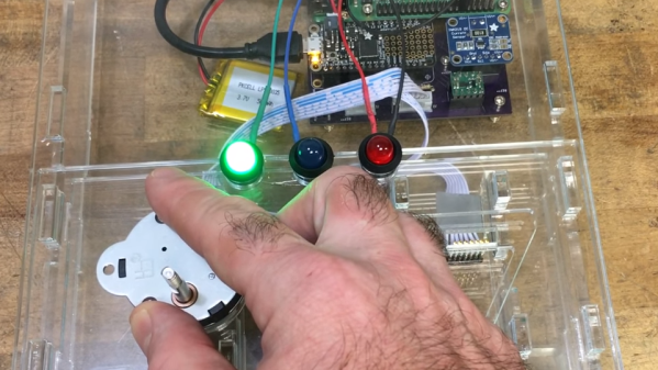
Folks from [Adafruit] are showing off a neat hack – USB host on RP2040, using the now-famous PIO peripheral. [Adafruit] builds a lot of RP2040 boards, and naturally, you gotta test them before you ship them to customers. They’ve been using very specific Teensies for that, and at some point, those became unobtainium. Based on the work of [sekigon-gonnoc] and with help of [Thach], they’ve made their TinyUSB library support bitbanging of USB over PIO, and successfully ported their test jig firmware to it!

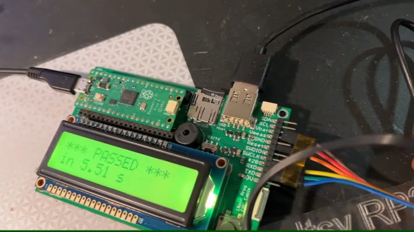
The base Pico-PIO-USB repo by [sekigon-gonnoc] shows a pretty impressive state of affairs – with low-speed and full-speed USB host and full-speed USB device modes supported, and quite a few examples to get you started. [Adafruit]’s work integrates this code into their TinyUSB stack, specifically focusing on MST (mass storage) features – as this is what you need to program a RP2040. Of course, they also provide a mass storage example to boot!

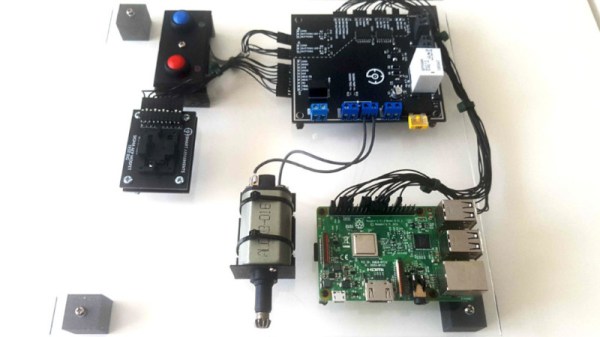
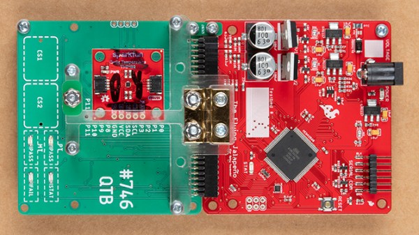
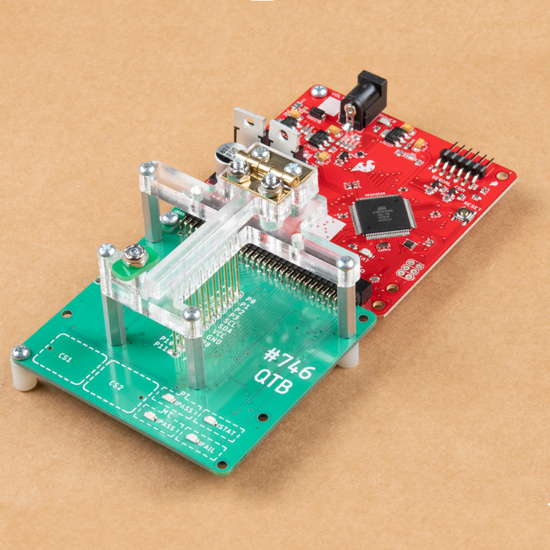
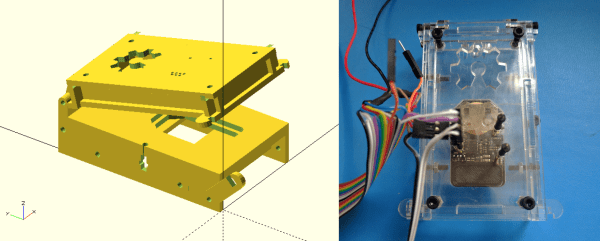
Test jigs are pretty important to have when making multiple pieces of a board, and with RP2040 supporting more and more interfaces thanks to PIO, it sounds like the perfect chip for your next production testing-intended PCB. With the jig brains taken care of, you’ll want to look into building no less important mechanical part, and we’ve covered quite a few ways to sort that out – here’s an OpenSCAD script that generates lasercutting files out of KiCad boards, or a jig built out of scrap copperclad FR4, and a pretty extensive tutorial on making your own lasercuttable jigs, to boot.

Continue reading “USB Host On RP2040 – With PIO”

A Budget Testing Rig For Low-Volume Production

It’s not unheard of for those who tinker in the land of electronics to suddenly find themselves with a project on their hands and potential customers clamoring at the door. Of course, the road to shipping a product is a long one, and requires a unique set of skills quite distinct from those required to build the initial prototype. In developing a product for Airsoft use, [bald greg] realized that a testing rig would be key to ensuring their hundreds of units left the building in working condition.

When shipping units in the hundreds rather than thousands, keeping overheads low is key to maintain a sustainable profit margin on each unit sold. Thus, [bald greg] built a rig that would allow for effective testing of devices rather than breaking the bank. The rig also handles programming, saving the cost of purchasing pre-programmed microcontrollers from the manufacturer. A Raspberry Pi runs the show, using its GPIO pins to program boards and saving test results and serial numbers for later reference. A bed of nails fixture is used to connect to each individual board. Additionally, to test each board as realistically as possible, hardware mimicking a real Airsoft electric pistol is used to properly load the hardware.

[bald greg]’s work is a great example of approaching QC on a budget, and we suspect he’ll sleep soundly knowing the boards in the mail are going to work first time. We’ve seen others take similar approaches, too. If you’re working on your own production testing rig, be sure to let us know!

Continue reading “A Budget Testing Rig For Low-Volume Production”

Building One Test Fixture To Rule Them All

Test and programming fixtures are great time-savers for anyone who needs to deal with more than a handful of PCBs. Instead of plugging in connectors (or awkwardly holding probe tips or wires) to program some firmware or run tests, one simply pops a PCB into a custom fixture with one hand, and sips a margarita with the other while a program decides whether everything is as it should be. Test fixtures tend to be custom-made for specific board layouts, meaning one tester is needed per board or device type, but this work is easily justified by the huge time savings they offer.

An inserted PCB sits atop the thick acrylic piece, with pogo pins making contact from below. Generous space on the left and right make sure there is clearance for any mounted components. Visible near the bottom of the green board are output LEDs, and two touch-sensitive pads.

But the fine folks at Sparkfun’s quality control department figured they could save even more time by exploiting common design features across different boards, and shared details about designing a single test fixture flexible enough to handle multiple board types and designs.

The test unit looks like pretty familiar stuff at first glance: some hardware responsible for running the test program, laser-cut acrylic jig to hold a test PCB in a consistent position, spring-loaded pogo pins to make temporary electrical connections, and LEDs to clearly indicate PASS and FAIL states. The clever part is the way the fixture is designed to accommodate multiple board designs, and how it uses several 74LVC4066 quad bilateral switch ICs to take care of switching which pogo pins are connected and to where.

As mentioned, to be compatible with multiple boards there must be common design elements to exploit. In Sparkfun’s case, the through-hole connections on their breakout boards are all in a row with standard 0.1″ spacing. By using the aforementioned pogo pins and 4066 ICs, different pinouts can be accommodated and multiple board types can be used without any need to swap to different test hardware.

Test and programming fixtures, being one-offs, tend to have a lot of space for creativity and often show clever design or re-purposing of parts. Our own [Bob Baddeley] explains all about them here.

Process Characterization On The Cheap With A Custom Test Rig

Testing is a key part of any product development cycle. Done right, it turns up unknown bugs and problems, and allows for them to be fixed prior to shipment. However, it can be a costly and time-consuming process. The [Bay Libre] team needed to do some work on power management, but the hardware required was just a little on the expensive side. What else does a hacker do, but build their own?

Enter the Thermo-Regulated Power Measurement Platform. It’s a device designed to control the die temperature of a chip during process characterization. This is where a chip, in this case the iMX8MQ, is run at a variety of temperatures, voltages, and frequencies to determine its performance under various conditions. This data guides the parameters used to run the chip in actual use, to best manage its power consumption and thermal performance.

The rig consists of a Peltier element with controller, a heatsink, and a fan. This is lashed up to a series of Python scripts that both control the chip temperature and run through the various testing regimes. Thanks to this automation, what would normally be a day’s work for an engineer can now be completed in just two hours.

Through a few smart component choices, the team accomplished the job at around one-tenth of the cost of commercial grade hardware. Granted, the average hacker probably won’t find themselves doing process characterization for cutting-edge silicon on a regular basis. Still, this project shows the value in building custom hardware to ease the testing process.

Testing is key to success in production. Custom jigs can make for light work when large orders come in, and we’ve run a primer on various testing techniques, too.

A Peek Into A Weed-Eating Robot’s Test Fixtures

When it comes to production, fast is good! But right the first time is better. Anything that helps prevent rework down the line is worth investing in. Some of the best tools to catch problems are good test fixtures. The folks at Tertill (a solar-powered robot for killing weeds that kickstarted last year) took the time to share two brief videos of DIY test fixtures they use to test components before assembly.

The videos are short, but they demonstrate all the things that make a good test: on the motor tester there are no connectors or wires to fiddle with, the test starts automatically, and there is clear feedback via prominent LEDs. The UI board tester also starts automatically and has unambiguous LED feedback, and sports a custom board holder with a recess just the right shape for the PCB. Once the board is in, the sled is pushed like a drawer to make contact with the test hardware and begin the test. The perfectly formed recesses in both units serve another function as well; they act as a go/no-go test for the physical shape of the components and contacts being tested.

Both videos are embedded below; and while there isn’t much detail on the actual test hardware, we do spy a Raspberry Pi and at least two Adafruit logos among other hacker-familiar elements like laser-cut acrylic, 3D printed plastic, pogo pins, and a PVC junction box.

Continue reading “A Peek Into A Weed-Eating Robot’s Test Fixtures”

OpenFixture Takes The Pain Out Of Pogo Pins

[Elliot] (no relation, but hey, cool name!) wrote in with his OpenFixture model for OpenSCAD. It’s awesome because it takes a small problem, that nonetheless could consume an entire day, and solves it neatly. And that problem is making jigs to test assembled electrical products: a PCB test fixture.

In the PCB design software, you simply note down the locations of the test points and feed these into the OpenSCAD model. ([Elliot] shows you exactly how to do it using KiCAD.) There are a few more parameters of the model that you can tweak to match your particulars, but you should have a DXF outline for a test jig in short order. Cut that out, assemble, and test.

If you have to make more than a few handfuls of a complicated circuit, it becomes worth it to start thinking about testing them systematically. And with this OpenSCAD model, you can have the test jig up and running before the first prototype boards are back in from the fab. How cool is that?

Tools Of The Trade – Test And Programming

In our final installment of Tools of the Trade (with respect to circuit board assembly), we’ll look at how the circuit board is tested and programmed. At this point in the process, the board has been fully assembled with both through hole and surface mount components, and it needs to be verified before shipping or putting it inside an enclosure. We may have already handled some of the verification step in an earlier episode on inspection of the board, but this step is testing the final PCB. Depending on scale, budget, and complexity, there are all kinds of ways to skin this cat.

Continue reading “Tools Of The Trade – Test And Programming”