Automate Your Pin Header Chopping Chores Away

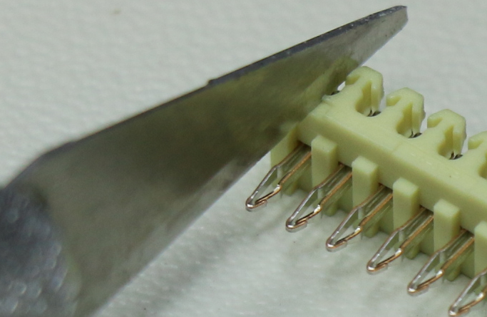
In most cases, cutting pin headers is a pretty simple job to tackle with a pair of cutters or even your bare fingers. But if you’re doing a lot of it, like for kitting up lots of projects for customers, then you might want to look at something like this automatic pin header cutter.

Even if you don’t need to follow [Mr. Innovative]’s lead on this, it’s worth taking a look at the video below, which has a couple of cool ideas that are probably applicable to other automation projects, especially those where lots of small parts are handled. Processing begins with a hopper that holds a stack of header strips over what we’d call a “reverse guillotine,” consisting of a spring-loaded plunger riding on a cam. A header strip is pushed out of the hopper to expose the specified number of terminals, the cam rotates and raises the plunger, and the correct length header is snapped off.

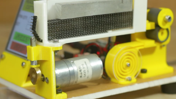
For our money, the neatest part of this build is the feed mechanism for the hopper. Rather than anything complicated like a rack-and-pinion, [Mr. Innovative] opted for a pusher made from a stiff yet flexible strip of plastic, which is forced along the bottom of the hopper by a pair of stepper-driven drive rollers. The plastic pusher is stored rolled up in a spiral fixture so it doesn’t take up much room.

Overall, it’s a simple and largely effective design. [Mr. Innovative] does express a little dissatisfaction with some aspects of the build, though; it looks like the stack of header strips needs a little weight on top of it to keep them feeding properly, and we notice a couple of iterations of the cutting mechanism in the video. The cut headers do seem to either fly off into the stratosphere or stay attached to each other, which could lead to jamming problems.

But still, it’s a solid design and reminds us of some other projects by [Mr. Innovative], like this SMD tape slicer or a CNC gear cutter.

Continue reading “Automate Your Pin Header Chopping Chores Away”

Using Fishing Wire To Hold In Pin Headers Is A Nifty Trick

Working on a breadboard, one can get used to the benefits of being able to readily plug and unplug jumper wires to reconfigure a project. One could only dream of doing so with PCBs, right? Wrong! [Stewart Russell] recently shared a tip on Twitter on how to do just that, with the help of a little fishing wire.

The wire can be neatly threaded through the board to enable quick hookups.

The trick is simple: on any old development board that uses 0.1″ pitch headers, simply weave some fishing line through the plated through-holes in the PCB. Then, regular jumper wires can be inserted just like on a breadboard. The fishing wire has just enough give to allow the jumper wires to be jammed in, holding them steady and in good contact, while still allowing them to be easily removed.

[Hackspace Magazine] has raved about the trick, noting great success using 0.38 mm fishing line. Alternative methods involve using toothpicks, though we suspect solution is likely messier and less reliable.

If you’ve got your own tricks for prototyping quickly using development and breakout boards, be sure to share them below in the comments. Alternatively, send your best stuff to us on the tipsline!

Hackaday Prize Entry: You Know, For Kids

Like the fictitious invention of the Hula Hoop in Hudsucker Proxy, [David Spinden]’s big idea is small and obvious once you’ve seen it. And we’re not saying that’s a bad thing at all. What he’s done is to make a new kind of prototyping connector; one that hooks into a through-plated hole like a pogo pin, but in the horizontal direction.

9092981463539177581This means that your test-points can do double duty as header connectors, when you need to make something more permanent, or vice-versa. That’s a lot of flexibility for a little wire, and it takes one more (mildly annoying) step out of prototyping — populating headers.

[David] makes them out of readily available header pins that already have the desired spring-like profile, and simply cuts them out and connects them to a standard Dupont-style hookup wire. Great stuff.

When we opened up the “Anything Goes” category for the Hackaday Prize, we meant it. We’re excited to see people entering large and small ideas that improve the world, even if it’s just the world of hackers.

Continue reading “Hackaday Prize Entry: You Know, For Kids”

Make Dual Pin Header Footprints Into Breadboard Friendly DIP

[John] wrote in with a solution to a prototyping issue that has vexed us for quite some time. Above you can see the DIP friendly solution for dual-row pin headers which he came up with. With just a bit of easy soldering he now has a breadboard friendly device for prototyping.

He starts by soldering a dual row pin header on the board, then clips off all of the legs on the outside row. The row of legs that remain are then inserted into one side of the trench on his breadboard. The other side of the trench has a single row pin header, and he solders them to the outer row on the breakout board using another single pin header aligned horizontally. This isn’t a 100% convenient solution, as it’s still pretty hard to get your jumper wires in the breadboard on the side covered by the breakout board. But if you plan in advance you can place your wires first, then plug in the development board.

Here [John] is working with TI’s eZ430-RF2500 board. We’d like to go back and remove the dual pin socket we soldered on our eZ430-F2013, replacing it with this style of pins.

Pin Header Sizing Machine

[Ammon Allgaier] built a tool that can break apart pin headers with a high level of precision. In the video after the break he demonstrates the built-in features. They include an adjustable stop to select the number of pins you’d like in each chopped segment. There’s also a small groove in the input side which the plastic frame of the header rides in. Just insert until it is touching the stop, and push down to break the header at the correct location. A couple of springs return the cutting tooth to its resting position, allowing you to make quick work of chipping up a 40-pin blank. This machine will become a nice companion for that automatic wire cutter.

This is great for single headers but we’ve long been on the lookout for a reliable way to snap off double pin headers. Far too often we make mistakes when trying to use two pair of pliers. If you know of a better way, please share your method in the comments.

Continue reading “Pin Header Sizing Machine”

Button Cell Connectors For Breadboarding

We’re working on a project that has a battery backup, but we don’t have any more coin cell holders on hand. No problem, we remember seeing a double pin header used for this. But when we tried to shove the CR2032 battery in between the pins it was a no-go. We could swear we’d featured a project that does this but couldn’t find it here at Hackaday. After much searching we came up with the Guerrilla battery holder which is seen on the left. No wonder it wasn’t working, the CR1212 in that picture is a much smaller package. So we figured we’d have to come up with something else, until inspiration struck.

There must be some other way to configure the pin header to work with a fatter cell body. On the right you can see that a diagonal orientation works like a charm. Join us after the break for a couple of close-ups of that connector and our thoughts on using this with a variety of different cells.

Continue reading “Button Cell Connectors For Breadboarding”

5×2 Patch Board

Sometimes we want to sit on the back porch, crack a beer, and do some prototyping. Other times we’d like to do the same but on the couch in the livingroom. To that end we added a 5×2 pin to 10×1 pin patch board to our solderless breadboard.

The 5×2 pin form factor is pretty common, used as an AVR programming header, on development boards like the Dragon Rider 500 and the STK 500, and in small prototyping devices like the Bus Pirate. We like the freedom of using IDC cables as interconnects and that’s where this board comes in. Now we can patch into the IDC cables yet still quickly disconnect them when moving to a different prototyping location. Check out the PCB artwork and this handy device in use after the break.

Continue reading “5×2 Patch Board”