Continuing his tradition of making bits of wire and scraps of wood work wonders, [HomoFaciens] is back with a unique and clever design for an electromechanical encoder.
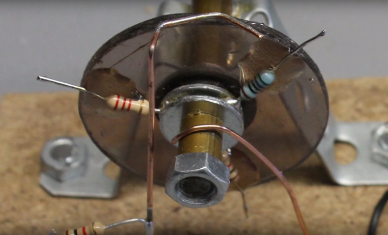
There are lots of ways to build an encoder, and this is one we haven’t seen before. Not intended in any way to be a practical engineered solution, [HomoFaciens]’ build log and the video below document his approach. Using a rotating disc divided into segments by three, six or eight resistors, the encoder works by adding each resistor into a voltage divider as the disc is turned. An Arduino reads the output of the voltage divider and determines the direction of rotation by comparing the sequence of voltages. More resistors mean higher resolution but decreased maximum shaft speed due to the software debouncing of the wiped contacts. [HomoFaciens] has covered ground like this before with his tutorial on optical encoders, but this is a new twist – sort of a low-resolution continuous-rotation potentiometer. It’s a simple concept, a good review of voltage dividers, and a unique way to sense shaft rotation.
Is this all really basic stuff? Yep. Is it practical in any way? Probably not, although we’ll lay odds that these encoders find their way into a future [HomoFaciens] CNC build. Is it a well-executed, neat idea? Oh yeah.


If your wheel was a stack of discs, each had conductive points (and internal resistor), you could make a “music box” with lots of spring leads. could even just use a 555 and use the resistor to change the output frequency.
I’m definitely stealing this idea at some point… Maybe when I finish all my other projects ;) (yeah, haha). Sounds really cool, I’d actually like to see this on action.
Although another idea I had would be to maybe use a “multi track” tape of these with two ends joined together forming a loop or something as well.
Interesting idea. An LDR, an LED and a printed encoder pattern could accomplish the same task
No, you won’t get clean transitions with an optical sensor. With the resistor wheel you have either a fixed or infinite resistance in your path. With the optical version the reading on a transition between two patterns could be anything in the range between both patterns.
That’s why they invented the Gray code.
But grey code is usually read by two optical sensors if you need continuous rotation encoders. The trick is that just one (analog) input pin is needed with this electromechanical encoder wheel.
Connect the outputs of a grey code optical/mechanical switch to a R/2R resistor network and read it with an A/D input.
Quadrature is read by 2 inputs. Gray’s input count depends on the required resolution.
That’s about as macgyvered as it gets.
I do consider my-self “estupido” in hw .. but i was laying the other night in bed and thinking how expensieve the “endless” rotaries are … and came up with something similar in mind :) definitely not macgyverish stuff
Educational for those new to electronics, I suppose.
Why don’t you entertain us with your expertise and knowledge instead?
I’m your little huckleberry. How does it differ from a 6 winding pot? Except with this it is harder to tell the direction of rotation.
Yes, but also an option for ambitious projects if you run out of pins on your microcontroller. This rotary encoder just needs one (analog) pin to detect movement in either direction.
Thanks Dan for promoting another project. Meanwhile I have tested the encoder wheel in a simple control loop:
https://youtu.be/IgU__c4NgrM?t=5m51s
It might be an option for a simple machine – let’s see what future ideas will bring to live…
Terminator close….. ? just observing… :)
I *knew* you’d have it in an actual build within a week. OP delivers!
This is actually interesting. what if you could use optical mouse parts for 3d printer encoding? i’ve got a box of optical mice. looks like a hackaday.io project already has this idea. ;) https://hackaday.io/project/1544-cheap-and-easy-to-build-3d-printer
I am not sure if the optical mouse will be a good choice for a linear sensor. My concerns are that “steps” are lost, thus when moving forward 100mm and back 100mm does the sensor find exactly back to the starting point? That’s what I will try to find out in the near future.
This guy’s fun but I think he’s messing with us with that accent
Well, all my videos are freely available, thus they can be remixed with a new audio track. I would appreciate to see one of them being reused with a better English audio ;-)
Well your English is far better than my German (since I don’t speak German) but there might be something off with the way you encode the audio because the timbre of your voice seems off, I can’t put my finger on it but I bet you sound better in real life.
So he has three testicles, get over it.
Damn it, I mentally read that reply with your voice… I really love your stuff Norbert!!! It’s just when I hear you voice I sort of backfill my own terrible Arnold Schwarzenegger impression in my head and try to talk along with you :) Keep on doing what your doing don’t ever change a goddamn thing -good on ya mate!
Maybe I’ll do a “Boots n Pants” Geico-esqe remix one day of your stuff, but don’t hold your breath :)
Can’t wait to hear you talking Schwarzenegger :-))
There is something wrong with all Americans. We all can do Schwarzenegger. “I’ll be back” i’m sure everyone just read that in Schwarzenegger voice.
@marco, man i did the same thing reading his comments. and yes i feel like he is too? but why? Feels forced right.
GET IN DA CHOPPA!!
Nah man, love the audio. You sound just like a guy I know that we call the Jolly German.
…maybe because I am just another jolly German. Watch out we are anywhere ;)
Just like in Klondike Kat … “Savoir Faire is anywhere” ;)
You could also have two contacts that were wheels on either side of a disk that has a labyrinthine track path on it so that the resistance on one side fell as it rose on the other and these were compared with two AD ports, or perhaps a simple circuit that fed a final value to a single AD port. Not sure how the noise level would be but with averaging techniques this should be manageable. The above method also tells you exactly where the shaft rotation is at all times.
The trick is to use just ONE analog input. Your idea results in a mechanism that’s more complex than a simple quadrature encoder.
Yes, noise is a huge problem with all electromechanical solutions…
If the wheels are actually cylinders of the right size there is always one part of the contact touching part of the track, this reduces noise and eliminates bounces, and as I pointed out, you can use only one ADC, at the price of a small amount of additional parts. At 10 bits on the ADC accuracy to 1 degree is possible. The reason I mention it at all is that this article is about methods using resistors, and that is what the tracks are. Obviously no system with contacts is ideal because they all wear out, but designing an ideal system isn’t the point here.
Not getting your angle here, sounds like a you’re describing a linear pot mounted on a drum?
No, it is just that a thin wheel has a point where it can sort of bounce as it goes over the gap between the arms of the track unless it is wide enough so that it can be positioned so that one part is still in contact at all times. If the track was more resistive than a simple copper track it could just run parallel to the circumference of the disk, but if you want a simple design that you can just etch on double sided PCB material you need to make the effective length of the track longer, which creates the other problem that is solved by the wider wheel contact.
I guess I understand what your tracks would look like, but there is also contact bounce whenever new “switches” are closed on whatever track you create, even if there is still another connection to the track without a change in switching state. It’s time for you to turn your idea into practice and do some experiments…
There is no bounce like you get with isolated switches as there is always a continuous circuit, there is just noise and that is at a frequency and amplitude that is so different from the data rate and signal level that it can be filtered out by the usual RC means. Also keep in mind that there are two paths on either side of the disk with the resistance arranged deferentially so for the total system there is no bounce on the same scale as a single isolated switch. Having two fat contact wheels on either side allows you to use a single spring to cause the contact head to pinch the wheel with a constant pressure on both sides at all times. The track is radial wedges that are alternatively connected at the top and bottom (labyrinthine) so they get very thin near the disk centre/shaft where no contact occurs, but this is desirable because the resistance is inversely proportional to the track cross-section.
I hope that additional explanation assists your endeavours to visualise the mechanism better, otherwise I’ll need to find the time to draw it.
I did a rough diagram of the track, it has a spacing error so it may not be usable as it but you can clearly see how it works. N.B. the blue horizontal lines that show the levels for the two contact wheels (there are three in total if you use both sides of the wheel with the track pattern mirrored) the lower wheel is “fat” so part of it is always in contact with the track, and the upper wheel is always on the circumferential part of the track, treat that as ground.
You can always cut off the inner parts of the track spokes and have SMD resistors there to turn it into a version of your idea, because they are closely related.
Here is the image, I hope it works,
http://i.imgur.com/AYHACcf.jpg
Your picture contains an error and can’t be displayed. Maybe you have to build one of your switches to prove you are right…
Works fine here, using firefox, are you using chrome?
http://i.imgur.com/AYHACcf.jpg
I can see that error it comes and goes! Click on the link and hit f5 and you can see it, either HAD, imgr or the internet is broken :-)
I put it on another host to see if that helps
http://oi66.tinypic.com/28lexqq.jpg
Now the drawing is displayed. Interesting pattern and I can see what you’d like to create. That could be a solution for mass production of this type of encoder. Still there will be bouncing whenever the contact wheel touches one of the “pikes” or brakes that contact. I don’t know if the bouncing characteristic of wheel contacts is better than that of wipers.
If the wheel is always in contact at some point, it’s shaft is vertical and the contact is diagonal there will always be a circuit to prevent even a micro arc, so if there is noise it will be at a much lower level. There is always a path from the wheel to the track, and air gab never opens up completely.
I should write some Python or OpenSCAD code to parametrically generate the resistor track pattern. There are improvements to the top contacting area I can make too, and the long path should probably ziz-zag as if travels down the wedge area to maximise the length. Not sure how thin I can get the tracks with a DIY toner transfer type PCB etch, but that is the idea. When you want an encoder for a “dumb” motor that can use no components other than the Analog In of an ATTiny. I think that gives you just enough ports to take commands via 2 wires, drive the motor F and R with two more, and have 1 for position sensing. I don’t have a pressing need to do it “right now” but the idea is very interesting so I thought if I shared it with you guys people could pick it up and improve it further, let it evolve.
There is a difference in potential when making or braking contact with a pike, thus the mechanism of contact bounce is identical to that of a normal switch. If you argue that there is a lower difference in potential, well you could also operate my wheel with lower input voltage.
But there is just a single track the entire pattern is a continuous circuit, contact is never completely broken because just before the fat wheel leaves one part it is contacting the next part. the difference in current is not from 0% to 100% like in a switch, it is the difference between the current determined by the resistance and one point on the track and the next segment, which is a small fraction of the entire track length. The voltage drop change is tiny, a few percent. The area of contact between the wheel and the contact area is always greater than the thinnest part of the track.
Remember the wheel is fat so the contact area is indicated by the red area in this animation. A normal wheel would be a dot not a bar. And yeah I know it would be even thinner but so would the tracks at the bottom, the animation is to get the idea across.
http://oi67.tinypic.com/311kite.jpg
Now I see where you’d like to add the wheel. Your argument is lower difference in potential. Let’s say input voltage is 5V, potential at wheel 2V and 2.5V when making contact with the next peak of the track, thus we get a difference of 0.5V. Well in principle you can operate my simple wheel with an input voltage of 0.5V to get something similar.
Except it would be 5/40 (0.125) volts drop per step for that particular wheel and there would be subtle inductance and capacitance effects caused by the wheel track layout as the current flow changes paths rather than switching on and off completely. An ideal track design would have 360 steps so the steps are less than 0.01 volts or between 2 and 3 times less resolution than the 10 bit converter can handle. Assuming total drop over the entire track is 5 volts. You’d need to scale everything correctly to get the most out of the Analog Input.
As I said before it is very much like your idea, but inside out and with way more resistors, plus that trick with how the contact works. Except it doesn’t need actual discreet resistor components. It should be better as it has less parts and less friction, as well as much greater resolution. And that is ignoring the noise and bounce difference as they seem to be disputed. :-)
Two things to consider:
1.) There is one transition in your track from 5V to (nearly 0V) when the wheel goes from end to start. At this transition you get all the contact bounce.
2.) Noise reduces the number of peaks your microcontroller can resolve.
Finally your construction is a potentiometer except that there are quantum steps instead of a smooth transition from 0V to Vinput.
Yes it is like lots of little resistors and there is never a broken circuit so the noise should be lower and the bounce likewise for each side. You can also ignore false readings more easily when you have all that positional information and you are using both sides of the PCB arranged so that the major voltage transition is 180 degrees apart. This is why I mentioned two sides up in the initial comment. I am still sure that just with a 2 sided PCB and contact wheels feeding two analog inputs you get 1 degree position accuracy at all times and no significant problems with noise or bounce. You can have 2.5 bits of noise and still have an accurate reading. With 2 inputs you are even more accurate as they can be average, that means up to 5 bits of noise is not an issue, over the total 20 bits of readings. Two sided PCB may rule out the ATTiny at the MCU for a DIY smart motor, unless it talks via 1 wire, which is possible.
Two normal potentiometers with a 180 degree offset will do exactly the same.
If you don’t trust me, build your encoder wheel and prove that I am wrong.
Yes they will work almost the same way, they are both forms of variable resistors, not exactly the same but very similar, except then you will need two pots, and good quality ones that have as little friction as the wheel on wheel method or they will wear out very quickly in a CNC design. And those twp pots need to be designed so that you can put them inline on the same shaft otherwise the configuration gets even more complex and requires gears etc. The wheel method is ideal for very low budget DIY projects, that is all, because optical methods is always going to beat it over all. However if you can half the cost of building a 3D printer, that will matter a lot to some people who are not well resourced. That would be a great thing to do for the children of the third world.
Another thing for CNC designs is keep it simple. Even the “third world” students I am in contact with have access to broken printers, thus salvaging optical sensors is no problem (which is why I made another video about reusing those sensors). The wheels on wheel encoder is more an academical problem to solve. If you think your design is a better choice than using “normal” potentiometers, take that challenge and tell me about your results.
Those other videos were great. Optical is the way to go if you can salvage the parts, it is smart to utilise the embodied accuracy of somebody else’s industrial complex. As for the resistor method, yes it is just an oddity that may have use in some exceptional circumstance, or for teaching how a pot works. I’m not even sure if I can source pots that can sit on a shaft without needing a gear on the shaft and a gear for each shaft of the pot. I should pull a few apart and see if you can run a shaft right through them, that would save a lot of effort. We have our own household wiki here, I’ll list it as an exploration the kids can challenge themselves with.
1. This is gorgeous…sexy even.
2. If this guy is not wearing lederhosen and holding a pint then the whole world is a lie.
Only Bavarians wear Lederhosen – I am a Hesse!
That’s a huge difference for all Germans !!!!!!!!!!!
…and we drink Äppelwoi (cider)!!!
For many Americans, the view of German culture leans Bavarian, probably due to Oktoberfest.
Perhaps Hesse could begin a massive annual cider drinking party?
…maybe I should start creating a Äbbelwoi brewing machine instead of the CNC series, because if all those tourists start drinking cider there might be not enough left over for me ;)
Love it! Very clever!
Suggestion: decrease mechanical losses between the resistor leads and the voltage divider by printing the desired number of bare traces and interrupting each trace reasonably near to the inside of the wheel with a surface-mount resistor. The contactors could be small copper finger-stock or carbon brushes. The contact patches would be on a bare section each radial closer to the outside edge of the wheel (so no discernable height change for the contactor, as it is not contacting any part of the resistor body). Thus, significantly reduced mechanical losses in the contacts. An additional benefit would be the ability to arrange the radials on a perfectly even basis even with a high quantity of radials, or the ability to do non-linear attachments (logarithmic sequencing perhaps, or eccentric… whatever you need your encoder to do). Fascinating possibilities here!
arrangements, not attachments. Stoopit spellcheck!
Yes, the build quality and so the electric properties of my build are a nightmare. I was surprised that it worked in the simple control loop I have build for a linear drive (see video link in a comment above).
A simple way to get better mechanical quality is using a commercially available electromechanical quadrature switch and add two different resistors (e.g. 1k and 2k) on the outputs forming a voltage divider with another 1k resistor whenever an output is in close position. I will demonstrate that in a future video.
simple, lovely, ehh maybe more
His voice reminds me of the guy the does this: https://www.youtube.com/user/VectrexRoli
He sounds totally different – He’s an Austrian. Can’t you hear the difference in accent? Clean your ears ;)
I’ve always heard the Austrian accent described as “sing-song”. I hear what that means now.
FWIW I used to work with an Austrian guy who once told me he was overheard by a stranger on the beach who instantly recognized his accent as a particular region of Austria. I was baffled by that until I realized how easily I can discern a Boston accent from a Providence accent. It’s all about what you’ve grown up with, I guess.
Of course I grew up in Connecticut, so I have no discernible accent. Wicked no accent.
I know what you are talking about, we Hessians are the ones that speak accent free German ;))
Norbert, have you considered doing the same thing with capacitance? A small metal plate would be fixed, with a bunch of metal plates attached to the resistors on the wheel. As the rotating plates pass the fixed plate they form a temporary capacitor. The fixed plate could have a layer of paper to act as a dielectric. Then the circuit becomes a resistor, capacitor, and another resistor. The debounce would be replaced with the first derivative of the voltage.
Well, you would need an extremely precise “switch”. Remember that capacitance changes with distance between the plates. Another thing is that the capacitance changes while the moving plates slide along the fixed one. You need an alternating current to “connect” the circuit. I guess that won’t work in practice – at least not in a simple McGyver way ;)
The changing capacitance is a feature, not a bug. AC is easy, since you already have a clock pin on the Arduino, though you’d probably have to connect that to a transistor. And you’d still only be using one wire for sensing.
I prefer simplicity over complexity. That wheel was meant to be a simple rotary encoder…
My McGyver toolbox isn’t suitable to create something precise as you suggest, thus its your turn to show that it works – just build it!
along the same lines you could use simple RC circuit to debounce the signal. Maybe even add a schmitt trigger to the circuit. It adds complexity over software debounce. but if tuned right might increase speed of the encoder. mechanical switches…so many problems. could do a SR Flip Flop debounce circuit too. then you need some nand gates..Might be worth it if you need low power processing of an input. like something with a battery that moves real slow. think solar power tracker? but for hardware cost software is the best solution i guess.
Should see what we are doing at work with a direct drive motor. cant say much more since it’s going through patent right now….man i want to say more but everything i type i feel is too much info. oh well.
Of course, the typical debounce circuits will work with this wheel, too. I will write about my investigations concerning speed limits of that simple wheel in a future log.
…and of course I am preparing for a patent lawsuit ;)
I’m guessing that Resistor matrix ROMs could be built using a similar idea. for added bonus, adjust the number of possibilities of resistor values and how many of these form a word. Now you can build your own 14-19 bit word ROMs which could be interesting. No need to use only 8 bit or 16 bit ROM storage l ;)
Or you could also use a Resistor tape (or Resistor tape loop) ROM where it’s read like magnetic audio tape, but with the Resistor tape and the Resistor values under the “read head” (resistance sensor of some kind).