Hall Effect Module Knows Where Your Motor Is

If you have a motor and you’d like to know where the shaft position is, you are likely to turn to an optical encoder scheme. However, as [lingib] points out, you can also use a magnet and a magnetometer. You can see how it works in the video below.

The MLX90393 is a 3-axis hall effect device and, with a magnet on the shaft, the X and Y outputs of the spinning magnet will form a quadrature output that you can easily read.

Continue reading “Hall Effect Module Knows Where Your Motor Is”

Use A Brushless Motor As A Rotary Encoder

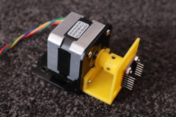
The electric motor is the fundamental building block of almost all robotic projects but, without some form of feedback, it lacks the precise positional control required for the task. Small servos from the modelling world will often use a potentiometer to sense where they are on their travel, while more accomplished motors will employ some form of shaft encoder.

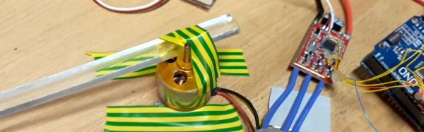
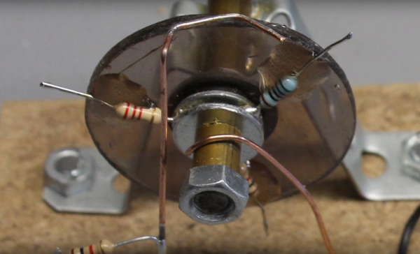
Commercial shaft encoders use magnets and Hall-effect sensors, or optical sensors and encoder discs. But these can be quite expensive, so [Hello1024] hacked together an alternative in an afternoon. It uses another motor as the encoder, taking advantage of the minute changes in inductance as the magnet passes each of its coils. It’s a technique that works better with cheaper motors, as their magnets are more imperfect than those on their expensive cousins.

The sensing is rather clever in its economy, sending a pulse to the motor through an off the shelf motor controller and measuring the time it takes to decay through the body diode of the driving MOSFET. It requires a calibration procedure before first use, and it is stressed that the whole thing is very much still in beta, but it’s a very impressive hack nevertheless. He’s posted a video demonstration which you can see below the break.

Continue reading “Use A Brushless Motor As A Rotary Encoder”

Wheel Of Resistors Form Unique Rotary Encoder

Continuing his tradition of making bits of wire and scraps of wood work wonders, [HomoFaciens] is back with a unique and clever design for an electromechanical encoder.

There are lots of ways to build an encoder, and this is one we haven’t seen before. Not intended in any way to be a practical engineered solution, [HomoFaciens]’ build log and the video below document his approach. Using a rotating disc divided into segments by three, six or eight resistors, the encoder works by adding each resistor into a voltage divider as the disc is turned. An Arduino reads the output of the voltage divider and determines the direction of rotation by comparing the sequence of voltages. More resistors mean higher resolution but decreased maximum shaft speed due to the software debouncing of the wiped contacts. [HomoFaciens] has covered ground like this before with his tutorial on optical encoders, but this is a new twist – sort of a low-resolution continuous-rotation potentiometer. It’s a simple concept, a good review of voltage dividers, and a unique way to sense shaft rotation.

Is this all really basic stuff? Yep. Is it practical in any way? Probably not, although we’ll lay odds that these encoders find their way into a future [HomoFaciens] CNC build. Is it a well-executed, neat idea? Oh yeah.

Continue reading “Wheel Of Resistors Form Unique Rotary Encoder”