Just in case you imagine that those of us who write for Hackaday are among the elite of engineering talent who never put a foot wrong and whose benches see a succession of perfectly executed builds and amazing hacks, let me disabuse you of that notion with an ignominious failure of my own.
I was building an electronic kit, a few weeks ago. It’s a modular design with multiple cards on a backplane, though since in due course you’ll see a review of it here I’ll save you its details until that moment. In my several decades of electronic endeavours I have built many kits, so this one as a through-hole design on the standard 0.1″ pitch should have presented me with no issues at all. Sadly though it didn’t work out that way.
Things started to go wrong towards the end of the build, I noticed that the temperature regulator on my soldering iron had failed at some point during its construction. Most of it had thus been soldered at a worryingly high temperature, so I was faced with a lot of solder joints to go over and rework in case any of them had been rendered dry by the excessive heat.
In due course when I powered my completed kit up, nothing worked. It must have been the extra heat, I thought, so out came the desolder braid and yet again I reworked the whole kit. Still no joy. Firing up my oscilloscope I could see things happening on its clock and data lines so there was hope, but this wasn’t a kit that was responding to therapy. A long conversation with the (very patient) kit manufacturer left me having followed up a selection of avenues, all to no avail. By this time a couple of weeks of on-and-off diagnostics had come and gone, and I was getting desperate. Somehow I’d cooked this thing with my faulty iron, and there was no way to find the culprit.
On our hackspace open night I was sitting with the kit in front of me looking again at its various signals. I took out the multimeter and set about the painstaking task of tracing the continuity of every single one of my reworked joints, convinced that way I’d find the ones that were dry. And I wasn’t disappointed, for between a line on the outer backplane socket and the same one on its neighbours I found no circuit. My culprit at last! Then I found another, and another. An entire bus, disconnected from the rest of the sockets. A horrible suspicion began to form, and I took a closer look at the backplane.
This backplane had its start on earlier versions of this kit as a piece of stripboard. You bought the daughter boards, and supplied your own stripboard. I’d naively assumed that the backplane was simply equivalent to a fancy piece of stripboard, but I was wrong. What I had assumed was space for a socket to take the bus away to another board turned out instead to be space for a set of jumpers which isolated the bus on the final socket. In some applications they could be filled with resistors, all I needed was a set of jumpers and my final board would be able to talk to its neighbours. I fitted a double row of pins and installed the jumpers, and as if by magic the kit worked.
So what can I take away from all this? First of all, the jumpers are there in the schematic in the kit instructions, and it’s clear what they do. So I failed to spot that, due to my having seen the previous stripboard versions of the kit. Secondly, I latched onto my faulty iron as the obvious culprit and didn’t look hard enough for anything else. Confirmation bias, you have claimed another victim!
If I can leave anything for you to take away, it’s that we here at Hackaday have to eat our own dog food when it comes to our failures, and that as I have just discovered it’s all too easy to read the instructions without really having read them at all. The next time any of us have a seemingly insoluble fault whose cause we’re convinced we have a handle on we should all try to take a step back and consider whether we’ve got it right or whether we’re barking up the wrong tree. After all, it could save us all the embarrassment of a public fail like the one described here, and that’s got to be worth the effort!
Jumper image: By Anthrax11 [CC BY-SA 4.0], via Wikimedia Commons.
And of course, my apologies to the Sultans of Ping FC for the title of this piece.
 Fail of the Week is a Hackaday column which celebrates failure as a learning tool. Help keep the fun rolling by writing about your own failures and sending us a link to the story — or sending in links to fail write ups you find in your Internet travels.


I’ve recently helped to debug a DIY USB hub on a FE1.1s IC (I didn’t make the board, my friend designed it and paid a board house to make it). Wasn’t enumerating, and voltage on built-in regulators was 3.4V and 4.4V instead of 1.8V and 3.3V. I’ve compared it to multiple schematics on the web, tried running with external regulators and without them, fixed a couple more problems in the process… Long story short, the GND from the IC wasn’t connected to board’s GND anywhere. Didn’t bother to check for that among the first basic things to be checked, and it wasn’t that apparent – there was a ground polygon and my intuition just told me there had to be a via. The ICs we used survived all of the abuse we put them through, surprisingly
I build an oscillator circuit that involved current mirrors for an adjustable current sink made out of a bunch of BC547s. It worked but the waveform adjustment was highly non-linear.
After hours of head scratching and checking every component, turns out there was one BC557 in the bunch.
Urgh. Been there. Done that. I forgot to connect the ground of SRAM chip on a PCB. At slow speeds, it did actually work which was surprising. I assume leakage through the address/data lines was just enough to power the chip at low speeds.
It probably had diode clamped inputs so as long as you have a low and a high on inputs you have some voltage. Then when it runs faster it drains more current and fails.
I saw one project here where the four pins on each end of a DIP micro-controller were literally cut of when the ends of the chip were hacksawed off. The power pins were on the ends so the diode clamping was used with two inputs to power the chip.
Made a circuit board once, came back with one of the ic pins not connected to the ground plane. looked at the signal name in eagle: GND\
it looked fine on my schematic where I label all the nets to prevent stuff like this because the eagle schematic editor doesnt render the \ slash, but still accepts it for use in a different net name
A group of us 30 minutes excitedly typing in Pacman written in basic from a computer magazine into a borrowed from a tech club’s bbc model A computer back when it was new and thats how mag’s distributed cover software. 8 hours later after checking and rechecking, someone in the room notices that they’ve put no u in colour in the mag listing, and in fact it was color in some places and color in others and being british our brain’s had just fixed the spelling on the fly randomly. BBC Basic iii fixed that later and they became interchangeable, so wonder if we weren’t the only people frustrated by it.
8 hours later and it was magical and caused me to rush out and buy a zx81.
The quickest way to fix a bug or hardware problem is to get someone to look at it fresh, fresh eyes seeing it for the first time and their brain hasn’t had time to filter off and miss the obvious. I’ve done this many a time and the feeling of having it fixed far outweighs the dent to your ego when its something daft and obvious.
Fresh eyes are always welcome. Had this happen a few times in the computer lab back in college. A friend would just get up and say, I’m going to get us some sodas, Kratz, fix my code, or something to that effect. Ah, good times college. Sodas, code, and friends. At least I still have soda and code.
Sometimes just trying to explain the problem to somebody else is enough for you to notice the mistake.
That’s pretty much the one thing I miss about working in an office with co-workers, “hey, look at my code, what am I not seeing”.
Typically the longer a bug takes to find… the simpler said bug is when you find it.
lol, then don’t look at any modern language like HTMP, PHP, Javascript etc they’re all spelt color.
It’s gotten to the point that I just accept the Americanism and write color on web sites like this even though that spelling is wrong in my location.
Funny, after years of reading Amiga Format and other UK computer magazines, and being on the internet for decades, I’ve started to randomly spell things with the British “u”. I still say and spell it “aluminum”, however.
lol, I owned a web design shop during the dot com boom and used all of those except htmp facetious :D
I know what you mean about altering for the audience, for a while I used to change all my dimensions from mm into imperial to post on machining websites as a lot of the audience is usually a non metric orientation, but now I just blast things out there in “commie” units warts and all. I am what I am, and people either accept it, or they don’t & their loss.
Dry joints because of a soldering iron being too hot?
You don’t solder much do you?
If you use an unregulated pencil iron this will probably be a surprise too.
I will ‘fess up here as well and say I, too, was surprised by the statement about a too-hot soldering iron running joints dry. In the 1990s my first exposure to electronics involved a retired WW2 Signal Corpsman (pensioner) who would make do with supplies on the cheap. He would find the irons from abandoned child’s woodburning kits for a quarter or fifty cents and use those. It seemed to be a bad idea to me, but he swore by them on those old blobby point-to-point tube radio circuits. (I mean, he’d fix ’em, and they played). Now, I everything I read about SMD work is that it is sometimes very, very intolerant of heat, (either excessive *or persistent* heat), and I can’t quite wrap my head around that fact and all the articles about people using toaster ovens and other informal methods for tiny component work and having any confidence that they have not ruined the circuit.
Too hot.. flux burns and smokes, solder doesn’t flow well past all of the caramel, lots of crispy bits on the board. Too cold, flux doesn’t flow, solder doesn’t adhere.. there’s a reason why you get temperature controlled irons, and OCD amongst the professionals when it comes to soldering. Having said that, you do need to get things pretty darned hot to burn the flux… take a look at a lot of hand built cheap Chinese goods if you want to see the full range of temperature related soldering screw ups. Get things really hot, and the tracks lift and the components blister.
And the board delaminates!
Here we actually call dry joints – “cold solder joints” but it’s true. An iron that is too hot will burn off the flux and promote oxidization. These often have a darker color than other solder joints.
The more common “dry joint” isn’t actually dry, it’s just cracked from repeated exposure to thermal cycles where the top of the temperature range makes the solder slightly malleable.
An actual “dry joint” is one where no – or too little flux was used when originally soldered and so the joint failed to “wet” – ie have an even flow from the improved viscosity that comes from the combination of surface tension and adhesion to the copper.
Ah. Glad I didn’t make a fool out of myself by admitting I didn’t know what “dry joints” are. I call them “cold” as well. Thanks for clearing that up. :-)
IMHO cold joints happen when one side is still cold enough to “repel” the hot solder. If you report that this happens with a HOT soldering iron, you’re not heating both sides but just one, and moving along before the other contact has warmed up.
How does a too hot iron cause dry joints? Is it because the flux burns off too fast or the solder takes too long to cool or what?
I suppose the solder oxidizes easily when it’s very hot, forming some sort of slag in the joint as well.
What’s being called “dry” joints in the article are also commonly known as “cold” joints.
This sounds like a RC2014 Z80 kit. Will have to await the review for confirmation! :D
Very nice kit if anybody is interested in this sort of thing.
:)
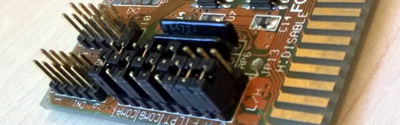
And hence the picture of an IBM AT era 16 bit (eISA) bus multi-io card to put as off!
Hmm…from the wiki: “A “dry joint” occurs when the cooling solder is moved, and often occurs because the joint moves when the soldering iron is removed from the joint.”
I’ve been doing this for ~50 years, first I’ve heard of a dry joint. Heard of “cold” solder joints, tombstone-ing, etc.
I guess too hot would allow the joint to move for a longer time after the iron was removed…
Lots of good examples here -> https://learn.adafruit.com/adafruit-guide-excellent-soldering/common-problems
Once you have been soldering for a while, you get a feel for it, and can pretty much solder smd with a blowtorch and a hot nail, but if you are looking for perfect results, every time, a temperature controlled iron or two helps no end.
I’m really bad at soldering, mostly because my hands shake too much.
Thank you very much for that link! I downloaded the PDF.
Seriously, thanks. :)
Random tip I give to people saying this, don’t be offended if you know this already but sit at your workbench with your forearms flat or supported in some way on the bench and maybe touch the heel of your palms on the surface too if you can, and get the articulation for the fine movement to manipulate the solder & iron onto the parts from just your wrist joints. Most people seem to find themselves a lot steadier for fine work doing this.
Probably Dry == Not Wetting.
Bingo. That is the original meaning of “dry joint” that is also now used for thermally fractured joints and oxidized joints.
……….
Dancing in the disco, bumper to bumper.
Wow! Seriously last place I expected to find Sultans fans. Can next article have a Smiths title, please?
Or maybe just Moone Boy fans?
That be me!
‘I Started Something I Couldn’t Finish’, perhaps?
Genius! And the only one I can think of, been racking my brain. Morrisey’s just not the engineer type.
:)
It’s alright to say things can only get better, you haven’t lost your brand new sweater. Jenny, you and me are gonna have to go gigging some time!
All seems a long time ago, dunnit.
Nah, last saw The Fall a couple of years ago. They’re still going. Happy Mondays too, and the Sultans, who I suppose are a bit skint. I’m 39 so I missed ’em first time round just a little bit, didn’t start going to concerts til my 20s. I mean it, if you wanna go see a band, I’m down in Kent, but get up to London now and then to see bands play. For some stupid reason I left my metropolis of a hometown in Yorkshire and moved to this shithole. Anyway…..
What is a dry joint? I have seen that several times lately and once in a video. Is it the same as what old-timers call a cold joint?
It’s the standard term for a failed solder joint. They look dull, rather than shiny. There’s a few variations on how to cause them, most soldering manuals cover it. Surprised you don’t know. Never heard “cold joint”, is that the same?
When did this term become standard? In over 40 years, I’ve never heard the term. Must be a Brit thing.
Cold jointmeans that the solder has not bonded to the surface because the temperature is too low.
It’s a pub with no beer, silly! And Slim Dusty will tell you, there’s nothing so lonesome than a pub with no beer!
On a more serious note, I’ve always understood the term to be “dry joint”, where the solder hasn’t adhered properly to both surfaces and so they’re just “in contact” and not actually properly bonded, leading to a connection that’s intermittent. Seems incorrect temperature (too hot or cold) can do this.
I have 2 Nissans and their tire pressure sensors malfunctioning, with a yellow light on a dashboard. Should I panic? If I would always drive a car with such sensors, I probably would. But other cars don’t have them and still fine! So I do not care. Same with soldering iron thermal regulator. When I was a kid, and then when I was a young engineer, even if some of my soldering irons had temperature control, they did not have temperature sensor or a fancy 3-digits indicator. Some of them were surely too hot. And guess what? I have seen plenty of cold joints, but never a dry one. You just move the soldering iron on (to the next pin) faster, and that’s it. To cause a dry joint, the iron shall glow red, I suppose. But you will have copper peeled off the board first.
Never!? You’re lucky. Any old cheap soldering iron can end up burning the board, lifting traces, etc. I suppose once you get good enough, it’s second nature, like typing, you don’t need to think about it too much. It’s a knack of getting the heat to the pin and board correct, getting the solder to flow right. I’ve knackered a few kits over the years. Fortunately you can usually hack a repair in, even if it’s a bit of wire or an intentional solder bridge.
You’d think they’d invent a higher temperature glue for PCBs just to stop traces lifting. I know just soldering it properly is a better solution, but it’s frustrating when you’re starting out. Like many things (including programming), I think soldering is easier when you’re taught by a human being, with a tight feedback loop to correct what you’re doing. My soldering is self-taught.
I think the cheapo soldering irons that are more likely to cause dry joints get thrown away or never used again once you’ve used a good soldering station with temp control.
I once got a ‘fried’ chip and suspected ESD or even a solar flair to be the cause. It turned out to be a missing jumper a collogue removed…
“Igor, I don’t understand it, I’ve check and rechecked everything in the monster and he’s still not alive, where have I gone wrong!?”, “Um, Doctor, the ECG is unplugged.” So I guess the lesson is check the simple stuff first?
The temperature can often become a problem …
In over sixty years of soldering professionally, and for personal projects, I’ve never seen more than two types of solder joints–good, and bad. The good ones are bright, shiny, smooth, with a minimum of solder used. The bad ones are dull and have a grainy texture (and are called COLD SOLDER JOINTS), may have too much solder, and may lift traces off the board due to the use of excessive heat. There are no other type of solder joints.
What in the bloody hell is a HOT SOLDER JOINT?
Dull, grainy, bad connection, like a dry joint. In this case because the iron heated up to glowing a dull red, that’s what happens when a Magnastat fails. With an iron in normal temperature range you’d never have this problem.
I think the fail here Jenny wasn’t the jumpers but that you didn’t catch onto to the iron playing up before you got to far AND you didn’t notice a problem with the flowing of the solder. ( or was there no real issue with the flowing of the solder in the first place ;) )
I’m sure I’m not the only one to have used a nail or screwdriver heated with a blow torch to get a job done.
Good on you though for been a good sport and bearing all to the hack a day vultures err commentators.
They don’t have to actually glow red. It’s possible to make dry joints just through bungling, though over-cooking the thing probably contributes. Any unregulated soldering iron ought to be able to make dry joints. Unfortunately.
Yes but surely I’m not the only one that inspects my handy work with a soldering iron as I’m going.
A failure get in manual soldering method is rather obvious at the time of making the joint.
It’s from a low temperature flux that burns off before the solder “wets” ie becomes adhered to the copper and “flows” along the surface like a “wet” liquid.
Flux is the variant here. I have a full roll of solder that I call “fuming death” because of the flux and that is why it’s still a full roll.
Well, it kindof IS a wet liquid, melted solder.
One of my commercial projects had a jumper that enabled the watchdog timer. The watchdog would reboot the system if the software locked up. We made use of this to download new software, for instance. Of course one of the units shipped without a jumper. Unfortunately this unit was installed on a mountain in Nevada. It required a helicopter to reach that unit in the middle of winter to install the jumper.
My biggest enemy is like this.
For me though it is “scenario completion* rather than Confirmation bias.
That is, I know the “scenario” because I have been here a thousand times before so I repeat the actions that most commonly resolved the scenario in the past but to no avail as the scenario that is present is not the scenario that I am attempting to complete.
Luckily for me, I recognize this situation (often very late) and restart diagnostics. My diagnostic process is preclusive before positive confirmation so that solves any situation. This diagnostic process comes from having to diagnose many intermittent faults.
I have never seen people so pedantic about the exact words used to describe a bad solder joint. And I’m constantly being accused of being to pedantic! Cold joint, dry joint, hot joint, etc.
In many decades of working on electronics, I’ve observed that both hobbyists and techs normally aren’t that picky about the exact terms. There are exceptions, of course. A technical paper will generally have more precise language, but even then many people call all bad solder joints a “cold” or “dry” solder joint and then go on to describe the exact cause.
But in terms of fixing a bad solder joint, the fix is pretty much the same regardless of the cause. Remove the old solder, clean, reflux if necessary, apply fresh solder.
Appearance and causes of bad solder joints:
1. No adhesion of solder to one or both surfaces caused by one or more:
a. Insufficient heat to the metal (iron not hot enough, insufficient time)
b. Insufficient flux
c. Dirty/corroded surfaces.
2. Grainy appearance and high resistance joint can be caused by:
a. Oxidized solder: Not cleaning tip just before soldering, adding solder to tip and trying to transfer from tip to joint, insufficient flux, excess tip temperature.
b. Movement of joint during cooling of the solder.
c. Repeated excess heat and/or vibration during operation of the circuit causing cracks in the solder, higher resistance contributes to heat in solder joint.
3. Joint looks good, but is intermittent or high resistance caused by:
a. Vibration exacerbating a joint that may have had insufficient solder or only partial adhesion. You may observe a dark ring around the component lead where the solder has cracked around the wire and is only making partial contact.
Sadly, a good lead-free solder joint has a slightly grainy appearance that is hard to distinguish from a leaded joint that was moved while the solder was cooling. Fresh leaded solder joints have a very shiny appearance, almost like drops of mercury. Even old leaded solder joints have shiny chrome-like appearance.
On a soldering iron tip, flux evaporates very quickly, and lead oxidizes on the surface in seconds. If you get a spike as you pull the soldering iron away, there is too much oxidization of the lead. You can remove the solder, clean the tip, and try again. Or you may clean the tip and add more solder/flux to clean the joint.
Solder oxidizing very quickly at melt temperature is why you never put your iron back without solder on the tip, and why you clean it immediately before soldering. Sometimes you may need to add some solder to the tip before cleaning just to get some new flux and unoxidized solder on the tip.
A higher tip temperature means you can solder more quickly, reducing heat transferred to the components. But the solder oxidizes more quickly, and you need to be quick or the increased temperature will end up transferring more heat to the components and possibly lifting the trace. I solder for a living, and I’ve had a lot of practice so with leaded solder I normally use 800F daily unless I’m soldering small surface mount parts.
For lead-free solder, the temperature is typically MUCH more critical. I have found that some formulations only work well across a 10 to 20F band of temperatures, and all require copious applications of additional flux.
Lady Ada has an excellent page with many pictures illustrating the appearance and causes of many types of bad solder joints:
https://learn.adafruit.com/adafruit-guide-excellent-soldering/common-problems