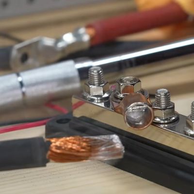
Let The Solder Scroll Take Care Of Your Feed Needs

[Victor]’s nifty tool the Solder Scroll is a handheld device that lets one feed solder out simply by turning something a little like a scroll wheel. It looks like an intuitive and comfortable design that can adapt to a wide variety of solder thicknesses, and is entirely 3D printed.

One part we particularly like is the feed system. One rolls a wheel which feeds solder out using a mechanism a lot like extrusion gears in many 3D printer hot ends. Both wheels have ridged surfaces that grip and feed the solder; their gears mesh with one another so that moving one moves both in unison.

Solder feed tools like this have seen all kinds of interesting designs, because while the problem is the same for everyone, there are all kinds of different ways to go about addressing it. We love this one, and we have seen many other takes that range from a powered, glove-mounted unit to an extremely simple tool with no moving parts. We’ve even seen a method of hacking a mechanical pencil into a new role as a solder feeder.

Let Your Finger Do The Soldering With Solder Sustainer V2

Soldering is easy, as long as you have one hand to hold the iron, one to hold the solder, and another to hold the workpiece. For those of us not so equipped, there’s the new and improved Solder Sustainer v2, which aims to free up one of however many hands you happen to have.

Eagle-eyed readers will probably recall an earlier version of Solder Sustainer, which made an appearance in last year’s Hackaday Prize in the “Gearing Up” round. At the time we wrote that it looked a bit like “the love child of a MIG welder and a tattoo machine.” This time around, [RoboticWorx] has rethought that concept and mounted the solder feeder on the back of a fingerless glove. The solder guide is a tube that clips to the user’s forefinger, which makes much finer control of where the solder meets the iron possible than with the previous version. The soldering iron itself is also no longer built into the tool, giving better control of the tip and letting you use your favorite iron, which itself is no small benefit.

Hats off to [RoboticWorx] for going back to the drawing board on this one. It isn’t easy to throw out most of your design and start over, but sometimes it just makes sense.

Continue reading “Let Your Finger Do The Soldering With Solder Sustainer V2”

Emergency DIP Pin Repair For Anyone

Who has not at some point in their lives experienced the horror of a pin on a DIP package breaking off? It’s generally game over, but what if you don’t have another chip handy to substitute? It’s time to carefully grind away some of the epoxy and solder on a new pin, as [Zafer Yildiz] has done in the video below the break.

The technique relies on the pins continuing horizontally inside the package , such that they provide a flat surface. He’s grinding with the disk on a rotary tool, we have to say we’d use one of the more delicate grinding heads for something more akin to a miniature die grinder.

Once the flat metal surface is exposed, the chip is placed in a socket, and a new pin is cut from the leg of a TO-220 power device. This is carefully bent over, inserted in the socket, and soldered into place. The whole socket and chip arrangement is then used in place of the chip, making for something a little bulky but one infinitely preferable to having to junk the device.

There are many useful skills to be learned when it comes to reworking, and we’ve covered a few in our time. Most recently we saw a guide to lifting SMD pins.

Continue reading “Emergency DIP Pin Repair For Anyone”

SMD Soldering, Without The Blobs

Hand soldering of surface mount components is a bread-and-butter task for anyone working with electronics in 2024. So many devices are simply no longer available in the older through-hole formats, and it’s now normal for even the most homebrew of circuits to use a PCB. But how do you solder your parts? If like us you put a blob of solder on a pad and drop the part into it, then [Mr. SolderFix] has some advice on a way to up your game.

The blob of solder method leaves a little more solder on the part than is optimal, sometimes a bulbous lump of the stuff. Instead, he puts a bit of flux on the pad and then applies a much smaller quantity of solder on the tip of his iron, resulting in a far better joint. As you can see in the video below, the difference is significant. He starts with passives, but then shows us the technique on a crystal, noting that it’s possible to get the solder on the top of these parts if too much is used. Yes, we’ve been there. Watch the whole video, and improve your surface mount soldering technique!

He’s someone we’ve featured before here at Hackaday, most recently in lifting surface mount IC pins.

Continue reading “SMD Soldering, Without The Blobs”

JBC soldering station sitting atop a custom switch box next to a selection of hot ends.

A 3-tool Selector Box For A JBC Soldering Station

Soldering is one of those jobs that are conceptually simple enough, but there’s quite a bit of devil in the detail and having precisely the right tool for the job in hand is essential for speed and quality of results. The higher-quality soldering stations have many options for the hot end, but switching from a simple pencil to hot tweezers often means unplugging one and reattaching the other, and hoping the station recognises the change and does the right thing. [Lajt] had three soldering options and a single output station. Their solution was a custom-built three-way frontend box that provides a push-button selection of the tool to be connected to the station sitting atop.

[Lajt] shows in the blog post how each of their target hot ends is wired and the connectivity the control station expects to determine what is plugged in. Failing to recognise a connected 50 W heating element as if the smaller 25 W unit was still connected would suck, with a huge amount of lag as the temperature of the hot end would fail to keep up with the thermal load during use. When connections are made, it is important to ensure the unit has sufficient time to detect the change in output and configure itself appropriately. An Arduino Pro mini handles the selection between outputs by driving a selection of relays with appropriate timing. An interesting detail here is what [Lajt] calls a ‘sacrificial relay’ in the common ground path, which has a greater contact rating than the others and acts as a secondary switch to save wear on the other relay contacts that would otherwise be hot-switched. All in all, a nicely executed project, which should offer years of service.

We like DIY tools and tool-related hacks. Here’s a DIY Hakko station, a Weller clone unit, and a peek inside TS1C portable unit.

Continue reading “A 3-tool Selector Box For A JBC Soldering Station”

Mapping The Nintendo Switch PCB

As electronics have advanced, they’ve not only gotten more powerful but smaller as well. This size is great for portability and speed but can make things like repair more inaccessible to those of us with only a simple soldering iron. Even simply figuring out what modern PCBs do is beyond most of our abilities due to the shrinking sizes. Thankfully, however, [μSoldering] has spent their career around state-of-the-art soldering equipment working on intricate PCBs with tiny surface-mount components and was just the person to document a complete netlist of the Nintendo Switch through meticulous testing, a special camera, and the use of a lot of very small wires.

The first part of reverse-engineering the Switch is to generate images of the PCBs. These images are taken at an astonishing 6,000 PPI and as a result are incredibly large files. But with that level of detail the process starts to come together. A special piece of software is used from there that allows point-and-click on the images to start to piece the puzzle together, and with an idea of where everything goes the build moves into the physical world.

[μSoldering] removes all of the parts on the PCBs with hot air and then meticulously wires them back up using a custom PCB that allows each connection to be wired up and checked one-by-one. With everything working the way it is meant to, a completed netlist documenting every single connection on the Switch hardware can finally be assembled.

The final documentation includes over two thousand photos and almost as many individual wires with over 30,000 solder joints. It’s an impressive body of work that [μSoldering] hopes will help others working with this hardware while at the same time keeping their specialized skills up-to-date. We also have fairly extensive documentation about some of the Switch’s on-board chips as well, further expanding our body of knowledge on how these gaming consoles work and how they’re put together.

Lift Those Pins With Ease

Reworking is one of the regular tasks of anyone who is involved in an electronic design process, because try as we might, it’s rare to get a design perfectly right the first time. Some reworking tasks are more difficult than others though, and we have to admit that lifting an IC pin doesn’t always result in success. But with this video from [Mr. SolderFix] there’s hope for conquering the technique, as he takes us through the best pin-raising technique on a variety of packages.

The trick it seems is to lift the pin first without attempting to disengage it from the molten solder, then returning to it with some copper braid to remove the solder and leave it raised. Once the secret is revealed it’s so easy, something a Hackaday scribe should be able to do. He does sound a note of caution though, as some packages are prone to disintegrating when stressed. A broken SOT-23 is not something anyone likes to see through their magnifier.

His channel is full of such no-nonsense soldering advice, and should be a fascinating browse for many readers. Meanwhile we’ve covered quite a bit of rework technique ourselves, such as last year when we looked at BGA work.

Continue reading “Lift Those Pins With Ease”