Use of the global positioning system is all around us. From the satnav in your car to quadcopters hovering above a point, there are hundreds of ways we use the Global Positioning System every day. There are a few drawbacks to GPS: it takes a while to acquire a signal, GPS doesn’t work well indoors, and because nodes on the Internet of Things will be cheap, they probably won’t have a GPS receiver.
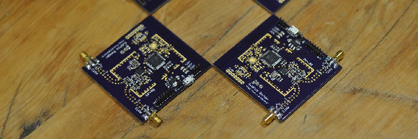
These facts open up the door for a new kind of positioning system. A local positioning system that uses hardware devices already have, but is still able to determine a location within a few feet. For his Hackaday Prize entry, [Blecky] is building the SubPos Ranger, a local positioning system based on 802.15.4 radios that still allows a device to determine its own location.
The SubPos Ranger is based on [Blecky]’s entry for the 2015 Hackaday Prize, SubPos that used WiFi, RSSI, and trilateration to determine a receiver’s position in reference to three or more base stations. It works remarkably well, even in places where GPS doesn’t, like parking garages and basements.
The SubPos Ranger is an extension of the WiFi-only SubPos, based on 802.15.4, and offers longer range and lower power than the WiFi-only SubPos system. It’s still capable of determining where a receiver is to within a few feet, making this the ideal solution for devices that need to know where are without relying on GPS.


So the WiFi access points need to broadcast a custom SSID, the first three letters in human readable form are “SPS”. and then other parts are in non human readable format – their latitude, longitude and height above or below (depending on the below sea level bit). And then the device calculates where it is in relation to the access points using multilateration (trilateration) by measuring the signal strengths of the access points.
The bit I do not get is if you are deep underground (away from GPS), how do you setup your initial reference points ?
It is a very interesting system.
You dig a tunnel straight up, put some GPS gear up the hole, and work out your reference from there. Just like any other underground project.
When they built the channel tunnel back in the 80s and 90s, they used this exact same method. They drilled a hole straight up into the English channel every few hundred feet to get a GPS signal. The tunnel flooded, divers went in, sealed the hole, and they pumped it out again. Repeat in another hundred feet.
Interestingly, each hole through the roof needed to be done by hand. The crew drew straws, and the short straw had to dig up into the English channel. The worker invariably died, but they got it done. Amazing feat of engineering.
Ah hahahahahahahaha!!!
Probably right.
And (true fact), that’s why this sort of navigation is called “dead reckoning”. Eventually they figured out how to do it without the, you know, dying, part, but the name stuck.
Really. ‘struth.
This also lead to the highly descriptive engineering term used to describe situations where the positioning work proved that they were in exactly the correct spot, i.e., they were “dead on”.
One problem with that is that water attenuates RF by a hell of lot, salt water even more. Once you go above 30 Hz (ELF) you may forget about trying to send RF through sea water. So even if I thought you were being half serious it still would not work. GPS L1 at 1575.42 MHz at ground level is around −127.5 dBm before being attenuated. And would be attenuated by to undetectable levels even by only travelling through a one meter of water ( http://users.tpg.com.au/users/ldbutler/Underwater_Communication.pdf linearly extrapolate the line out from 1MHz to 1575.42MHz ).
Can you cite your source for this information please ? I am very interrested by the technology used for building this tunnel.
However, the channel tunnel was opened in 1994 (https://en.wikipedia.org/wiki/Channel_Tunnel) while the GPS seems to have been operational only since 1995 (https://en.wikipedia.org/wiki/Global_Positioning_System) so I doubt they used the ‘real’ GPS.
are you fucking kidding me?
Both my grandfathers *and* my fathers *and* my mom died setting up the GPS in the channel tunnel before I was born.
Now you know why there is a Benchoff Fan Club.
Hahaha multiple fathers, and your mother died before you were even born, I feel a conspiracy theory brewing! ;)
@Brian: Don’t bogart that joint, my friend.
I heard they used sharks.
With frickin’ laser beams.
How can you trust any positioning system that’s based on signal strength when obstacles will change this?
If you are taking readings from multiple sources, the intersection that each form will be a hyperbolic curve. And if there is an outlier, it just means that its region of certainty will be less well defined. The more readings you take the tighter the clustering will be. So with 20 sources in range, I think that the results will be extremely reasonable.
The Ranger solves this by performing a different method of distance measurement over just using RSSI. The Ranger however is designed more for hobbyist autonomous robotics, as you need a special client to take the measurements. Which is why I tried to make it as cheap as possible, without sacrificing measurement quality to make it more accessible to this audience. I’ll have a demo video up this week to show it working.
Maybe one could contact the original author for technical support, or ask for a refund on the RAT software.
You do it as it has been done since the time of the Pharaohs, incrementally from know reference points.
http://www.boeingconsult.com/tafe/ss&so/survey2/theodolite.htm
http://www.boeingconsult.com/tafe/ss&so/survey2/theodolite-basic450.gif
Or buy a tape measure.
This project deserve a prize!
And this man deserve a beer!
Haha thanks! I’ll take the beer :P
How does the different method of distance measurement work.
It uses a phase measurement technique to determine distance. I’ll have more details shortly, I’m just getting a demo video going. Essentially it works by measuring the phase angle of the waveform as it arrives at the receiver from the transmitter. The phase angle directly correlates to the distance. It’s similar to how some laser rangefinders work and is pretty stable.
How does this work when the phase of each wi-fi beacon is arbitrary and (in general) always shifting? Unlike (say) LORAN or similar schemes, the transmitter sites are not phase-locked.
The article is a bit misleading, there are two separate projects mentioned. Take a look at the Ranger project.
Darn. So I see now you’re using essentially a stock function of the chipset. Looking back through the begats I get to Atmel’s app note AVR2150, and all they say about the actual ranging method is “proprietary”. Is there any public information on how they actually perform the measurement?
At Motorola years ago (70s & 80s) we sold a “Mini-Ranger” harbour positioning system. Superseded now by GPS, it pinged a 5 GHz radar transponder and timed the reply, getting as low as 1 meter precision over several miles. Beat the snot out of the aviation equivalent, DME. After all these years, I wonder how different Atmel’s system really is from the Miini-Ranger (or aircraft DME, for that matter).
This is using their proprietary statically compiled library at the moment, but I am working to redevelop it (for example I have already got it running on the new MCU and am using the raw measurement values from it rather than what it spits out). The main issue is that the PMU isn’t well documented in the datasheet, but I am gradually putting it all together and getting it documented. I hope to release these boards soon so others can have a hand at it too as it’s a very under appreciated chipset. It’s a shame, because it would have sold tonnes back in 2013 when it was released if they opened this up.
There’s more info in the Atmel docs if you are interested – http://www.atmel.com/tools/REB233SMAD-EK.aspx?tab=documents
I wonder if accelerometers could be used to increase accuracy.
I have plans to put an accelerometer on the client to help with accuracy, but for the moment I’m just using raw measurements which are pretty stable on their own. It will mostly help with rapid movements due to the averaging that is going on, which stops you from getting smaller intermediate updates quickly (which you will get with the accelerometer). Baby steps :)
From my view pretty similar to c3nav (the navigation system on the 32c3 in Hamburg). It worked quite well (detection of floor+position via wlan acces points), and even included indoor routing support:
* https://github.com/nomoketo/c3nav
* https://events.ccc.de/2015/12/25/search-find-and-be-found-c3nav-32c3-indoor-navigation/
Apple has had this for a while for tracking iphones inside department stores…. called (drum roll) iBeacons. Beacon tech for stores is used for proximity location mainly, so for high accuracy, try drone or robot positioning systems like the one at https://www.pozyx.io/
This Ranger competes with the pozyx.io on price and has similar accuracy. It’s a hobbyist platform that will be available for less than a third of the cost of the pozyx system.
How does it compare in terms of latency though?
It calculates position instantly, so latency is only as bad as the distance measurement and client calculation, which takes about 120ms for the measurements and 80ms for the trilateration for 4 nodes.