It’s true that a lot of the projects we feature here (and build ourselves) are created to accomplish some sort of goal. But, many times the project itself is the goal. That’s the case with [Proto_G’s] self-oscillating pneumatic machine, which he built with no particular use in mind.
[Proto_G] started this project simply as an engineering exercise; he just wanted to see if he could make it work. That’s the kind of spirit we find very admirable — not every project needs to be the culmination of your life’s work. Sometimes, just doing the thing is motivation enough.
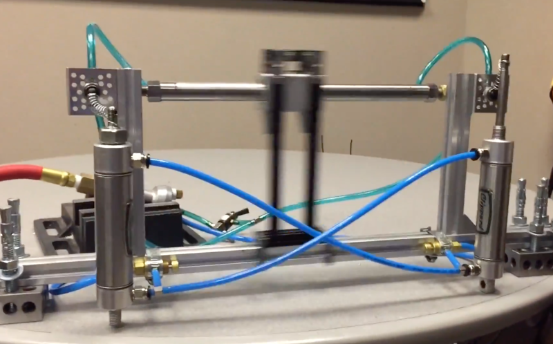
Like any good engineer, [Proto_G] thinks mechanisms and linkages are neat. And, even Hollywood agrees that an oscillating mechanism is not a trivial design. Adding pneumatics to the mix just adds to the interest. The basic idea is to switch opposing valves on and off when the carriage reaches each side, which is accomplished with pneumatic actuators which trigger air pressure in a “magnetically coupled rodless cylinder.”
The magnetically coupled rodless cylinder is a pretty interesting component, which utilizes a magnetic piston within the cylinder to move the magnetically coupled carriage on the outside of the cylinder. This lets the piston work with pressure in both directions, as both sides are sealed. Could this have been accomplished in other ways? Sure, it could. But, this way is pretty darn cool, and is something you can add to your list of mechanisms that you might use in future projects.
[via /r/engineering]


Can you make logic gates with this?
I’m also wondering about this. At any rate, I can imagine how to make a MOSFET-like structure using a simple momentary button (or one of the two air rams he indicates), hence CMOS should be possible (since both PMOS and NMOS are possible based on configuration of each button). Of course, it is very possible to make logic gates more simply (e.g. two normally-pass buttons in series for NAND, thus allowing any digital circuit).
However, if we take the pressure/voltage analogy, this is nothing short of a voltage-controlled oscillator. It would be cool to see a pneumatic-PLL using this and a pneumatic phase detector.
Many mechanical systems automatically implement something similar to a PLL. They always ackquire the lowest possible energetic state. Rotate a plate with three marbles on it (plate has a rim), and they will form a perfect triangle.
Have a look at this:
https://en.m.wikipedia.org/wiki/Centrifugal_governor
Such a governor comes close to a PLL, but instead of analyzing a phase difference it just relies upon energetic stability.
Ah, I can think of something similar to a PLL: The “normal clocks” as they were called here in germany. Those clocks were connected to a centrally controlled minute strobe. The seconds counting index rotated freely and was roughly calibrated to one minute. If the strobe arrived before it had completed its round it was forced to move to “12”; If the index was too quick it stopped at “12” until the strobe arrived. This PLL only knew two phases, but you can call it a true mechanical PLL. In some casey it was even pneumatically strobed.
Maybe a case for retrotech; Anyone listening?
Nahhh i prefer pneumatic PID loops!
That would just be a tweakable combination of highpass, lowpass and allpass, but pneumatically. The optional delay line is already covered by the upper machine. PID owns its wizardy attitude solely to the fact that analog filters are a wee bit harder to understand in the digital domain (and they are called integrators and diffentiators just to conform to mathematical language).
A main problem might be the unstable pressure values in pneumatic systems. A fluid based system would be more exact.
I really don’t get PID and PID math. It seems that PID tries to be a one size fits all.
I have no problem with closed loop control though. If I am heating a pot of solder and have a sensor on the other side of the pot to where the heater is then I have –
1) input power
2) delta t between current temp and target
3) Power loss as delta t between current temp and ambient
4) Time delay between the effect of added power and thermal conduction to sensor.
All these things can be calculated and a formula made that works perfectly without overshoot, without oscillation and without guess-working the three variables of PID.
So what is the point of PID? Is it just a generic solution that kinda works in most cases but isn’t perfect anywhere?
Perhaps you should attempt to better-understand PID before attempting to critique it. That formula that can be calculated and work perfectly without overshoot? It’s expressible using PID, for the simple dynamics you describe.
The point of PID is that it is a generic mechanism that can be mass-manufactured and applied to the control of just about anything.
Why would I bother to understand PID better if I can just make calculation based on the laws of physics? It sounds like a second rate technique.
And yes, a formula that works without overshoot, undershoot or oscillation! What then is the point of PID?
The laws of physics are remarkably concise lol.
See your system as a filter with a certain response, the PID is what is needed to make it respond the way you want it to respond, if you have perfect knowledge of the system the is no guess work, and even if you knowledge of the system isn’t perfect or slightly changing you get a good approximation
Your ad-hoc method also needs perfect knowledge of the system and all it’s variables, but if you get something slightly wrong or things change, like there is a draft, more or less solder in the pot etc. it might break it weird ways
Pneumatic logic is a well established industrial product.
Here’s a catalog link
https://www.parker.com/literature/Literature%20Files/pneumatic/Literature/Telepneumatic/PCC-4.pdf
Logic elements start on page A11.
We actually had a number of these in my middle school tech class. I remember making something like the above only it went much faster and was much louder.
Yeah and I actually have a pneumatic circuit board made with two halves of machined acrylic with different valves and air relays. It’s pretty interesting stuff.
Pneumatic logic is (or at least was) an industrial standard for environments which don’t allow electronics. I’ve seen some in a factory producing duct tape. The problem there was: The main solvent for the adhesive layer was gasoline, and the raw tape material was run through several machines for drying. Any spark would have ended the story rather impressively. So, how else do you control machines in such an environment?
During my college experience (Electro-mechanical Engineering Technician Robotics – say it fast three times) I actually built a basic ALU (arithmetic logic unit) out of pneumatic cylinders and various pilot valves. It was fairly limited, but it was expandable.. if you were truly insane a pneumatic computer is very possible. Once you devise a NAND gate, you can make all the gates you need.
There are a few companies that makes pneumatic logic devices, And, Or, you name it. I have a couple lying around somewhere….
Mythbusters did it already. :P
Makes you want to groove to the beat when he starts it up!
Ha Ha Ha … love it!
Thanks RÖB!
That’s a very complicated winding machine.
Why would you use a piston triggered by an endstop to trigger a switch ? While he could do it directly using proper endstops (1NO,1NC) ?
Anyway greetings for building it, whatever the purpose is.
Because piston actuated switches look way cooler!
It’s overly complicated on purpose, like a Rube Goldberg machine.
That’s a very interesting way of coupling the rams to the switches! Is that a typically done thing or just a hack? Can’t believe it actually works reliably at any speed!
Thank you, I’ve never seen it done like that before. It’s just something I came up with looking through my part drawers for an appropriate linkage. I was thinking of using a flexible flapper that would hit the switch on the way up and the way down but I like the springs better.
https://rctoymemories.com/2013/01/06/tomy-air-jammer-road-rammer-1980/
air powered toys from the 80’s
That was I toy I would love to have when I was a kid if I knew it existed (and was available in the Netherlands).
Also, great educational value!
Thanks for the link.
AirHogs made pneumatic airplanes in the late 90’s before turning to electric motors in the 2000s. They had a ‘RAID’ air powered engine that would run for a minute or so.
it would be funnier if there was a dildo attached to it.
Rule 34
This is so stupid you cannot not love it <3
This style engine was used to power steam railroad from the start of steam rail power through the early 20th century.
Close! This is a linear actuator. The railroads were rotational. The differences are in the valve timings and the fact that this is driven in both directions and a railroad locomotive piston is only driven in one direction.
linear vs. rotational is just a matter of adding a crank, and I think most locomotives had double acting cylinders
http://www.petersrailway.com/media/image/PR%201%20p90%20p91%20900%20wide%20cropped.jpg
In electronics, this is a bistable multivibrator. Even the shape of the mechanical one reminds me of the circuit diagram of the electrical version:
http://www.massmind.org/images/www/hobby_elec/e_ckt7_2.htm
Freaky.
Yup. The cylinder / switch thingies may as well be electric relays, out of which you can build any logic circuit.
It can also be seen as the probably biggest and loudest R/S flipflop with feedback through a delay line.
I just had a look at the Apple 2 schematics, and the clock unit is about the same.
The Apple II oscillator is quite a lot different. The astable multivabrator mentioned above is symmetrical. In the Apple II, half the circuit is an impedance buffer and the other half is a amplifier that is inverting with respect to the impedance buffer.
Are you sure?
I just found this one:
http://www.freeinfosociety.com/electronics/schemview.php?id=1472
The oscillator is in the lower left corner.
Ah, well, you’re probably right, it just looks symmetric. It’s not a flipflop plus feedback like the machine above.
Yep, that is the schematic I was looking at.
The transistor on the left is and impedance buffer and rail splitter. The transistor on the right is an amplifier that generates feedback to the left transistor (via current mirroring) that is inverted with respect to the left transistor.
It’s and interesting circuit and it does look similar to an astable multivibrator.
dual useless machine: https://youtu.be/UkgoSOSGrx4
Everyone working with pneumatic cylinder, and pneumatic logic has made a pneumatic oscillator !. In most case it was the result of some mistake. Pneumatic hammer use this kind of oscillator . In steam engine the air compressor of the steam engine was exactly a steam oscillator ( in French engineer slang petit cheval ) . There are also pneumatic pump used for sewage water exhaust working like that .
nice! I also tried this kind of oscillator some time ago in 2008, which worked a little faster but not as long ;) https://www.youtube.com/watch?v=ATasfQHh0hk
Wasn’t this already PATENTED by Apple an/or Microsoft (Et alia)?
You could use this to fire a pneumatic paintball gun automatically!
Coupling something useful onto it, it is the basis of a penumatic powered liquid pump.
Nasty chems and petrol and sewage can be pumped without electric power. The only time I saw one was on Junkyard Wars. They were part of the planted junk it seemed.
I’m going to look that up later; sounds fascinating.
I think there are river powered water pumps too.
They’re usually hydraulic rams, a different kind of thing. Though still fascinating, and a bit confusing to get your head round.
Thank you! Couldn’t remember what they were called.
I used to work construction, so ‘hydraulic ram’ means something that was a PITA to replace. ;)
I know of one that pumps water almost 200 foot up only on the flow of the creek. It has been going for over 50 years.
Man I miss that show…
Robot pr0n.
Attach a blade, make a guillotine.
I just saw this…
https://electrosome.com/wp-content/uploads/2012/11/astable-multivibrator-using-transistor-working-1.jpg
This “self oscillating machine” is also known as a “engine”- something that turns an energy source into repeated motion.