Magnetic gears are surprisingly unknown and used only in a few niche applications. Yet, their popularity is on the rise, and they are one of the slickest solutions for transmitting mechanical energy, converting rotational torque and RPM. Sooner or later, you’re bound to stumble upon them somewhere, so let’s check them out to see what they are and what they are good for.
What Are Magnetic Gears?

Where conventional gears use mating surfaces of mechanical interlocking teeth, magnetic gears employ alternating magnetic fields to transmit torque. For a long time, magnetic gears have only played a minor role in engineering. Their comparably high price, directly reflecting their dependence on rare earths like Neodymium, complex assemblies, and their tendency to slip at high torques hasn’t exactly pushed them into the spotlight. The achievable torque density of magnetic gears is indeed considerably lower than the one of their mechanical counterparts, although, on the plus side, they also do not suffer irreparable damage if their specified torque is exceeded. Currently, increasing the torque in magnetic gears is the subject of many research programs, and magnetic gears are finding their way into more applications.
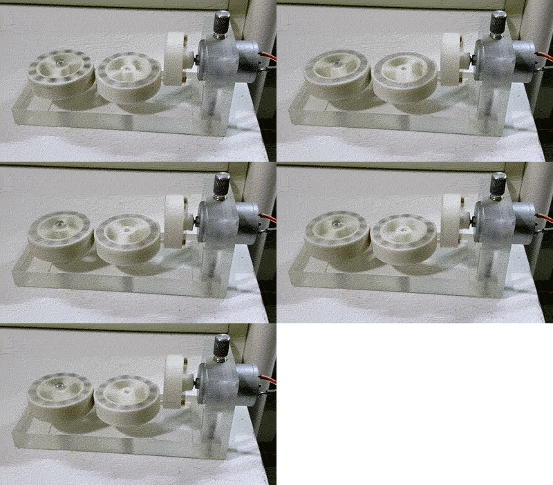
Because magnetic gears aren’t mechanically interlocking, with no physical contact between any of the rotors, they are not subject to mechanical wear. Most regular gear types, such as cogwheels and even worm gears, can be replicated as magnetic gears, simply by replacing the cut teeth with alternating magnetic poles of permanent magnets. The 3D printed, magnetic “cog wheel” assembly to the right is a great example of this.
However, in industrial applications, the term magnetic gear often implies a far better performing coaxial type, which you can see in the animations below. It is structurally very similar to a strain wave gear (i.e. the Harmonic Drive gear, also shown below) and allows for high gear ratios as well as comparably high torque. This type of gear relies on the flexibility of the magnetic field rather than on a flexible spline. Click on the animations of different gears below to see details about how they work:


As the inner, fast spinning magnet ring of the concentric, magnetic gear rotates, it forces the modulator ring, consisting of ferromagnetic steel pieces embedded in a non-magnetic tray, to mesh with the alternating magnetic field of the outer ring. Both the inner and outer ring are assembled from strong permanent magnets, and the numbers of pole pairs in the inner and outer ring as well as the number of iron pieces set the gear ratio. Due to the small air gap between all rings, there is no friction to account for. The actual implementation of such a gear may vary, and the modulator ring may either act as a stator or can be directly attached to the output shaft, with the outer magnet ring then acting as a stator.
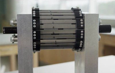
Coaxial magnetic gears can be extraordinarily efficient, almost maintenance free, have a very low torque ripple and find applications were those factors are an issue. At low speeds, they achieve efficiencies in the range of 99.9 %. The high gear ratio of magnetic gears makes them interesting for stepping up very slow input forces, such as ocean wave power, an application that has been explored by the UNC Coastal Studies Institute. The same benefits make them interesting for wind turbines as well.
Another application for magnetic gears is marine propulsion, where they are used to step down higher input RPM from an engine to the low RPM and high torque required for the propeller shaft. Earlier this year, Rolls-Royce, ATB Laurence Scott and magnetic gearbox manufacturer Magnomatics announced their plans to develop a magnetically geared propulsion system for ships. The ability of magnetic gears to hermetically seal the input and output forces is also useful in laboratory and medical environments.

Of course, magnetic gears have disadvantages, too. As mentioned, the maximum torque may not be sufficient for some applications, and they are expensive and typically heavier than regular gears. Also, at very high RPM, they lose their advantage of efficiency due to increased losses, caused by hysteresis and increased eddy currents in the modulator. Nevertheless, most of these limitations are slowly being removed by ongoing research. The programmable magnets by CMR allow for strong, fine pitched magnetic structures, which may allow for smaller, more efficient magnetic gears with higher torque density in the future. Also, the requirements for gears are changing. While more torque may always be better in industrial applications, interactive robotic applications require mechanisms that give in and ensure the safety of human users.
Magnetic gears can also be fabricated without the need for heavy gear-cutting machinery, which makes them especially interesting for DIY projects. A decent, concentric magnetic gear could be assembled from a bunch of permanent magnets, easily available hardware and 3D printed parts. What do our readers think, would you use a magnetic gear for a project? Did you encounter magnetic gears in applications I’ve missed here? Let us know and share your ideas in the comments!
Thanks to Hackaday.io member [magnets], who requested this post after seeing the video below:
Thanks to [Ralph Bijker] for creating the cog wheel rendering used in the header graphic!



Not sure if it counts as a gear, but IIRC my aquarium filter from years ago had a magnetic drive shaft to isolate the motor from the impeller (propeller?) unit that moved the water. The motor could thus be completely sealed from the water side.
That is a good use of a magnetic coupling, not a magnetic gear. If the pump somehow would need to be geared, you could add a normal gear before or after the magnetic coupling. If a magnetic gear was used to increase torque, than that gear would be at least as big as a magnetic coupling that could directly provide the required torque, and also have the same or better accuracy. It’s nice concept but I found it really hard to think of a practical use of a magnetic gear.
I think one of the big benefits is that there are no teeth that are meshing and producing wear; dually, it produces less friction as well
Almost no wear and very quiet operation. Also acts as a shock absorber if there is a jam.
I think some industrial shredders use this, but can’t find a video right now.
not a shock absorber but a slip clutch
I guess they would be a good replacement for belt drives. In machinery such as the PZ rotary/drum mower belt drives have to be used due to the high speed and inertia of the drums. There was a 4 belt version that would shear driveshafts. The 3 belt version was superior because it avoided this failure however they wear out many rubber belts. The high speed of the drums doesn’t require much torque so it would be interesting to see a design that used magnetic gears instead of gears and belt pulleys.
In the event the input shaft and the output shaft rotate at different speed it’s definitely a gear set. Respectfully you are comparing apple to oranges in your example.
AFAIK these are a lot like the magnetic stirrers used in labs. You have a coil, or several coils, driven by AC, as the stator, and housed in plastic, then the rotor is just a simple bar magnet. The difference is the rotor is outside the body of the motor rather than within it. For low-power waterproof applications it’s a good system. So it’s more of an inside-out motor, there’s no actual gearing.
The fact it will slip, if it gets jammed, rather than overheating and breaking, is an added bonus.
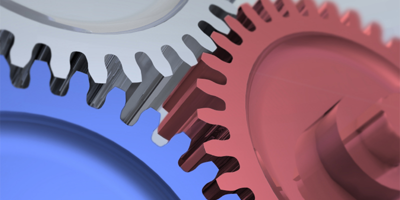
Thanks to [Ralph Bijker] for creating the ridiculous, laughable cog wheel rendering depicting gears that can’t actually turn used in the header graphic!
Actually I find it a great analog for the progress made on a project with one gear representing the team doing the work, another representing the project manager and the last gear representing upper management sticking their nose in all the time!
Nope it was Alvaro Heinzen in the EXIF data.
Sorry but I’m still not connived a magnetic gear has any advantage over with an electric motor. Essentially generating the magnetic fields for the last “gear” electrically instead of driving it from the previous gear. An electric motor is also frictionless if you ignore the shaft, and electromagnets can produce stronger and cheaper magnetic fields, and can be electronically controlled to any rotation position or frequency, and driver electronics can be very efficient too. I don’t see how a magnetic gear could provide more torque or more accurate control than an electric motor. There may be rare cases where you have to avoid conductors but somehow can tolerate magnets. Even without batteries, electric motors can be driven by a hand-cranked generator, which is actually used for emergency operation of sliding doors.
AFIK. the advantage is that rare earth magnets scale better to small sizes than electromagnets, and I think they can maintain higher average flux levels across an air gap. So nothing revolutionary, but useful where ever a hermetic seal, zero-wear, or torque limiting is needed.
Good point. That’s a bit like comparing apples and oranges: There’s nothing electric about the magnetic gear: The magnetic field change is produced and consumed by the gear, without the detour through an electric current (except for eddy current losses). Brushless DC motors output their peak power at very high RPMs, so if your application wants to stay on the ground, you need a gear of some sort.
My mind jumped on this band wagon too. I look at this and think that a “gear” laid out like the rotor in an electric motor where coils can be switched in groups would make for a variable-toothed gear and function effectively as a transmission.
Electric motors can be smaller and lighter if they run faster, right? So a small, fast motor, and gear it down, might be useful. For those gears, why not magnets? So there’s a use that’s better than “just use the right motor in the first place”.
That, and you might want to drive 2 things at different speeds from the motor. There’s all sorts of uses for gears, and these are just a different type of gear.
So… if I understand this correctly, the concept is to drive the stator and take output from the rotor, using the coils to “slip” the difference in rotational speed. Nice idea, but wouldn’t the coils get fried if the first time it gets a torque that stalls the motor?
Old car speedos use magnets to decouple the drive from the gearbox to the needle. The needle uses a spring to prevent it from spinning around and to give a crude measurement of speed of rotation.
The astounding thing about eddy-current/speedcup speedos (and tachs – lots of shaft-driven tachometers are still in use in light aircraft) is that they’re at all accurate, since you’re betting against a speeding ticket if it’s too far wrong and you don’t know how to correct for it.
It gets livelier when you start to factor in cruise control – I once drove a fleet car (a diesel Oldsmobile station wagon, which will tell how long ago that was) that had a speed control that would surge wildly every time you hit a bump and scared everyone to death. On examination, the factory had routed the original speedometer cable through a sensor box on the firewall, then through a secondary cable to the dash. The sensor box was, predictably, mounted on a thin tab of sheet metal and was quite heavy, so every time you hit a bump, the mount would flex, cables would bind, the engine would try to compensate by surging, then slowing wildly as the cable loosed up. (usually ± 20 mph!). I wedged a bunch of folded newspaper (remember those?) under it and it was fine from then on.
No, old car speedos use a spinning magnet (coupled to the car’s wheels via a flexible cable) to induce current in an aluminium needle assembly. The induced current forms a magnetic field and causes the needle to turn against a spring. The strength of the field (and thus the amount the needle moves) is proportional to the speed of the magnet.
less of a gear, more of a magnetic drive, magnetic clutch …
It has a fixed ratio that isn’t one.
Will magnetic bearings ever be a thing? I mean would they ever be able to be load bearing and low friction or friction free?
Magnetic bearings are used in a lot of thing, the thing is they are very specialized since they require electronics to control their position. Turbo pumps use them, among other things. The problem with them is power loss, loose power and the supported device drops. Older turbos used batteries for backup, newer ones generate power from the spinning rotor to power the bearings till it slows to a safe speed to land on the landing bearings.
This is fascinating, I love reading about odd mechanisms that aren’t typically shown in books. This is yet another reason why I love HackaDay! I think I may actually have a fairly practical use for this, or at the very least, it’s getting the (magnetic) gears turning in my head.. Back to the drawing board, maybe I’ll have something fun for you to post about in a couple months!
A question, though. If using permanent magnets, is there typically any degradation in the fields, such as if they are dropped or have something hit against them? Or if they are moving something that hits against something else?
As an extra bit of humor, I used to work at a design consultancy and would often be in long brainstorming sessions. One familiar joke we had was “once we start bringing up magnets and lasers, you know we’re out of ideas.” It’s nice to see practical, real world solutions using magnets, but always makes me laugh a bit.
Temperature kills them. On Rare earth its low, typically 90 degrees C will kill them.
Any thoughts on a magnetic CVT?
I was sitting on the other end of that cloud day dreaming bout the idea of a magnetic clutch for use in a car. Would allow you to be stupid with your left foot without smelling a dead clutch coming through the vents.
the problem any (purely) magnetic coupling capable of holding the torque of an engine, could provide greater power than the engine if used as a motor. so why bother with the engine.
Because the coupling isn’t a motor and doesn’t work as such?
Two discs of sufficient diameter with button magnets embedded around the rim will hold quite a bit of torque before they start to slip. If you wanted to use it as a motor, where would you put the wires in?
Magnetic powder clutches are a thing too! Typical application is a single motor driving two clutches to allow proportional electric control of drive power and direction. I have one in a 1966 military vehicle to rotate the turret.
That’s kind of what the Toyota Prius does. It has a planetary gear box with the engine and two electric motor/generators coupled to input shafts and the final drive coupled to the remaining shaft. The ratio of power input/extracted by the MGs sets the output speed. They can also spool up the IC engine, so at low speeds it can run completely on electric power, then start the engine when required.
This concept was used to interface to a flywheel to store energy in a vehicle by one of the big players in the UK. Theoretically great except that eddy currents ruin the efficiency at high speed.
And what I forgot to mention that this was a great way to pass the vacuum barrier in which the flywheel ran.
Of all the websites I know, hacks day is the last I would have expected to use the dreaded 3 interlocking gears as a title picture.
In fact, don’t I remember a post/rant about this on hackaday just a few months ago?
*Hackaday… Damn autocorrect on new phone.
New challenge everyone: make the 3 gears turn. Someone managed 3 LEDs / switches on one wire & battery, so I’m sure with some thought we can solve this, even if it does end up a bit Escher.
http://www.youtube.com/watch?v=5Mf0JpTI_gg
https://www.youtube.com/watch?v=5Mf0JpTI_gg someone beat us to it I’m afraid.
That’s pretty awesome, thanks!
Getting one to work feels like it’s the obvious mechanical analog to Fredzislaw100’s electronics puzzles…
magnets can also act as an overload protector by slipping the fields when the output is bound.
so on an electric bike you will not threaten to burn out the motor or controller if you are trying to climb too steep of a hill or you put on the brakes without releasing the throttle and for lower power kits you cant burn donuts or rubber
Yeah, this is the first advantage I thought about. Reminded me of the similar feature in electrics screwdriver.
The conversion to a motor looks interesting, but how is the speed controlled, like a stepper motor? Also how well do they handle heat, does it reduce the strength of the magnets?
There was a nice magnetic gear clock designed by Weston Bye and published in HOME SHOP MACHINIST magazine. Full plans are available and many have been built. See https://www.youtube.com/watch?v=_UhWgIN4izs for one example.
I wonder how this would perform for an LP player?
High speed motor coupled to a magnetic gearbox to reduce to the desired speed.
Small, high frequency vibration from the motor is easy to dampen and any RPM variations would be effectively geared down out of existance.
No cogging in the gears, no gears to wear and no belts to stretch and perish….
LP? You mean that old, outdated mechanical sound storage media? Would be a complete niche product these days.
Coolest thing I learned from this article was the magnetic viewing film (the green film in the demonstration). Looks like it is pretty cheap on eBay, less than 10 EUR.
I am convinced these are great.
“Would they ever be able to be load bearing and low friction or friction free?”
Yes, Yes and oh hell yes.
One. Small. Point. Murphy pointed out.. Temperature exchange. Running too hot and they loose all magnetism.
I’m curious, can this technology be used for a non rotating housing (housing remains geostationary) that is subjected to a reasonable amount of torque from the rotor?
160kg load magnetic gear drive components and assembly design