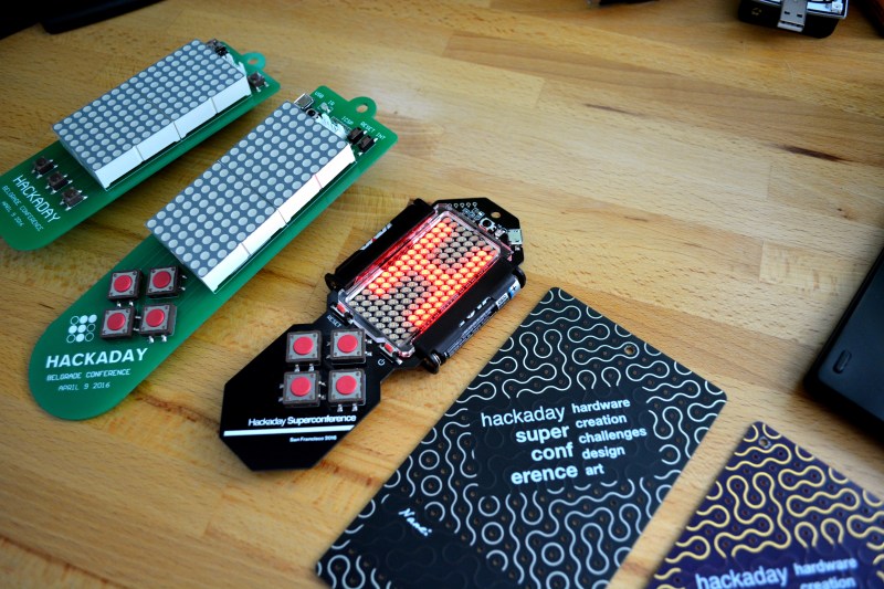
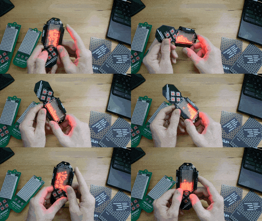
The 2016 Hackaday SuperConference is just around the corner and today we get a good look at the hardware badge. It was designed by [Voja Antonic] — a legend of hardware creation who will be at the conference. I like to think of him as the Woz of the Eastern Bloc, having designed the Galaksija computer. This badge is a beautiful example of embedded design. We’ll dive into all of the details after the break.
Get your ticket now for 48-hours of talks, workshops, the Hackaday Prize party, badge hacking, and so much more.
This badge hosts an 8×16 surface-mount LED matrix, four user buttons (plus reset and wake-from sleep), IR communications, and a three-axis accelerometer, all driven by a PIC18LF25K50, powered by two AAA batteries, and programmed via USB. That’s a mouthful of delightful hardware.

[Voja Antonic] based the design on the badge that he developed for the Hackaday Belgrade Conference in April (shown on the left). That was a stellar badge design, and [Voja] managed to improve on it for this one. I really like the edge-mounted single-AAA battery holders which, along with the replacement of the LED modules, cuts down on the thickness of the badge. They also reduce the weight, from 88 grams to 52 grams. Those with keen ears will note that I incorrectly quoted 62 grams in the video but the lower figure is correct.
There will be a few changes from what you see here. If you look closely you can see an acrylic bezel around the LEDs. On the final badge this will host an acrylic diffuser. This prototype, originally spun in June, has the incorrect location printed on it. The SuperCon will be in Pasadena, CA on November 5 & 6, 2016.
The badges are interactive. A kiosk at the conference will let you store your own scrolling messages on the badge. And if you’re really clever you can figure out how to make your badge prank those other people are wearing. The IR comms feature is also how you take part in the crypto challenge. [Voja] has cooked up some fun by placing badges around the conference with puzzles stored on them. Write a program to your badge to interact with them and decipher what is sent back. This was hugely popular in Belgrade and will be even better at SuperCon!
The nine-pin expansion header on the back is one more way that this badge is designed for hackability. We had such a great time last year with the bare-PCB hardware hacking it was important to provide direct access to the hardware on this badge. As with the amazing badge hacking of the Belgrade Conference, this badge is running a bootloader. It tends all of the hardware, providing memory-mapped access to the display, buttons, and peripherals. This means if you’ve never blinked an LED you will get up and running quickly. More seasoned programmers won’t have to get bogged down with low-level coding, and wizened experts can blow out the bootloader and go bare metal (don’t forget your PICkit).
I want to take a moment to showcase the craftsmanship of this badge. Check out the layout, and the aesthetic — this is a thing of beauty. Now take a really close look at that LED matrix (click to embiggen). When [Voja] first sent me the prototype I thought there was some solder balls stuck to the flux. Wrong. What looks like a stray cat hair or solder splash is a tiny wire — ninja-level rework that [Voja] performed by hand before shipping this my way. Check out some of the other projects he’s posts.
I love this badge. It really has pulled in the best of what we’ve done at the last two conferences. The only sure way to get your hands on one is to show up at SuperCon. Get your tickets now!
Spread the Word
Please help us get the word out about the 2016 Hackaday SuperConferene. Tell everyone you know and share http://hackaday.io/superconference on your social media. Thanks!


I’m not surprised that Voja created a work of art for the conference badge.
Voja, you need to do a write-up on your process! For example, where did the bezel come from?
Laser cut lexan/acrylic?
Two part? Bezel and cover glued together or just a bezel? Looks factory injection molded.
This is a one-piece bezel that was laser cut. The final badges should have a diffuser over the LEDs that glues to this bezel (serving as a spacer the height of the LEDs).
Excellent design. Especially the dense SMD LED matrix
Outstanding job !
When I look at his work, I always wonder wtf I’m doing in this field :) Luckily, there is a lot of work for all of us in electronics.
Yup, resistor ring painter here.
Boring and thankless job, but somebody has to do it!
Thankless is right, they only let me have the one brush so I have to rinse between colors. So if you get a bluey green or a reddish brown you have a hard time deciding on, it’s because they’re rushing me. I asked for one brush per color last year but the accountant went bezerk about a thousand percent increase in asset ratio or some nonsense.
Seriously? Why don’t they use any machines for that instead?
“don’t forget your PICkit”
Don’t forget your arduino – https://hackaday.io/project/8559-microchip-pic-arduino-based-programmer
I’ll have a couple of pickit3’s there but I’m fairly impressed by the list of devices that are supported by this project
NICE PROJECT
I wonder if it can be hacked into a POV display? That would be cool…
Put it on the end of a stick and baton twirl at just the right speed as a message scrolls on the LEDs
Interesting question. The display is being scanned by a serial to parallel LED driver. You’d need to overwrite the bootloader (which is easy to do with a PIC programmer) and then it would just be a matter of calculating the timing to make sure you could shift in the data fast enough. I think it should be possible.
So challenge issued, who’s going to turn the badge into a POV display at the con?
You can overwrite the bootloader, but if you don’t have the programmer you can also use the link at 0x1808 to redirect the existing ISR to your own routine, loaded by the bootloader.
The new Timer0 ISR routine should not have its own LED matrix service, I think that POV display should be driven outside the Timer0 interrupt. You can also use GPIO connector to input home (zero angle) signal from some optical or Hall Effect sensor to the MCU, in order to synchronize the display with the rotation. Theoretically you could also use the accelerometer data, but I’m not sure that it will offer the good angle accuracy.
“Woz of the Eastern Bloc” …. the author played Tetras too long, and lost the key.
So, when can I buy one on the Hackaday Store?
Can’t wait to to give them bubble physics and make them float. :) Voja, this is completely awesome!
As a continuation of our existing FireFly project seen here: http://lumipendant.com/
We have arrived at nearly identical hardware, 12×16 LED matrix on the HT1632, Accelerometer, Capacitive sense on the antenna, IR for coms, STM32F103C8 under the Arduino IDE.
Scrolling LED demo here: https://vimeo.com/185061929
This is amazing, not only FireFly V2, but also V1 is very similar to BalCCon badge (https://www.youtube.com/watch?v=IFifeMkfip8)
I like FireFly project. Nice video and beautiful music also
Oh that’s awesome :) I want one :>
I did something similar with the Defcon 15 badge. It also had a grid of surface mount LEDs. Added an accelerometer chip and did a bouncing pixel and a little sand particle thing: https://www.youtube.com/watch?v=naxq9KmJ3HM
Looks great! Do you know where I can find source code for sand particles and accelerometer?
Just curious, but how would one go about accessing the bootloader on these? Can they be programmed from the Arduino IDE or similar?
The bootloader acts as a USB drive you copy hex files to. You can download and use MPLAB X IDE, or Microchip’s online cloud IDE. Check out the project page for more info:
https://hackaday.io/project/16401-supercon-ii-badge
There is an example project you can use as a starting point here:
https://github.com/Hack-a-Day/2016-Hackaday-SuperConference-Badge-Hacking