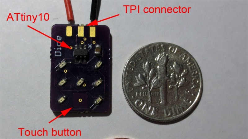
[Tim]’s Dice10 is an exercise in minimalism. Building an electronic dice using an ATtiny10 with code that fits within 1kB is not too difficult. Charlieplexing the LED’s would have used three of the four available GPIO pins. [Tim] upped the game by using just two GPIO pins to drive the seven LED’s for the dice. A third GPIO is used as a touch button input. Besides the ATtiny and the LED’s, the only other component used is a capacitor across the supply inputs.

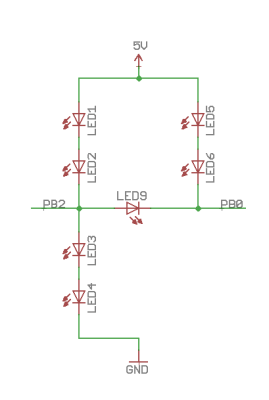
The LED’s are grouped in three pairs of two LED’s and a single centre LED. Usually, Charlieplexed LED’s are connected across pairs of GPIO pins. But his scheme includes connections to the 5V and GND terminals, besides the two GPIO pins. Building a truth table makes it easy to figure out what’s going on.
STATE PB2 PB0 LED's
1     Z   Z   --
2     L   Z   LED 1/2
3     H   Z   LED 3/4
4     Z   L   LED 5/6
5     Z   H   --
6     H   L   LED9
7     L   H   --
8     H   H   --
9     L   L   --
Only the logic states used are listed in the table. It’s possible to add two more LED’s between PB0 and GND and one more anti-parallel with LED9, making a total of 10 LED’s driven by two pins. That’s quite a hack. The important thing here is to have two LED’s in series in the arms that connect to either 5V or GND.
[Tim] has posted the code and hardware source files on his Github repo, and his blog post has some additional details on how he solved the problem.
If you’re looking for more inspirations on minimal dice designs, check this “PIC powered pair of electronic dice” which uses a PIC 12F629 with five outputs driving a pair of 7 pips to make a dual dice.

If you have a cool project in mind, there is still plenty of time to enter the 1 kB Challenge! Deadline is January 5, so check it out and fire up your assemblers!


Except that’s only four separate states, which could have been accomplished with standard charlieplexing. The second led in each leg doesn’t count.
(that said, his technique *is* useful, getting n^2+n states from n pins… it’s just that an electronic die doesn’t show it off.)
Ah blah, ignore me. Charlieplexing is n^2-n, not n^2.
I can do hundreds, maybe millions of LEDs* using only two pins. You might have heard of my method; It’s called I2C. I can also do it with USB. But where’s the fun in that?
* Not LED’s, LEDs.
Addressable leds (however it is rendered is entirely irrelevant) are only a new development, cost at least 2 orders of magnitude more than their dumb brethren and are significantly larger.
They also don’t generally talk I2C, and *certainly* don’t talk USB. Whatever controller you’ve got in the middle has to do that job.
(Also, holy comment necromancy Batman!)
Bah, I like reading old articles anyway!
Was also wondering what LEDS had USB capability; sounded very wrong.
I’m going through old articles :-) I can hook up many many dumb LEDs to another microcontroler (or more than one if cascaded) and control virtually limitless numbers of them. Could also do it over UART. TIMTOWTDI
Right, so why were you being critical?
Good thing I wasn’t being critical. Just saying TIMTOWTDI is all.
Bullshit clickbait posting. While the technique used here is kinda nice and creative it is really “just” controlling four *sets* of LEDs. The title implies 7 individually controllable LEDs.
I can controll 512 (or any number) LEDs with a single pin. Just parallel them, of put in series on an open collector output. :-)
Charlieplexing allows n^2-n LED’s per n I/O.
[Tim]’s scheme allows n^2+n LED’s per n I/O.
Technically, he can control up to 6 sets of LED’s using 2 I/O’s, but the Dice project doesn’t need to use all. 4 sets are enough. The caveat is that the string between Supply/GND and an I/O needs to have 2 LED’s, while the string between 2 I/O’s needs to have just one. He’s posted details here : https://cpldcpu.com/2015/05/24/plexingplus/
Having said that, I think a more appropriate title would’ve been “6 LED’s, 2 Pins– beat that, Charlieplexing”
I don’t understand the truth table. Especially states 8 and 9. What is it about PB0 being high that stops a high PB2 from lighting 3 and 4? And wouldn’t PB0 and PB2 being low light up 1, 2, 5, 6?
Voltage drop. I think the idea is that you shouldn’t put in any other states than both high-z or the states that turn the leds on. The other states are simply not used, or could just be used as needed (although that would need the rate modified to maintain consistent brightness)
State #8 lights up LED 3/4, and state #9 lights up 1/2/5/6. But these, along with states #5 and #7 are not used for the project (not needed). [Tim] has posted a detailed explanation here : https://cpldcpu.com/2015/05/24/plexingplus/
Is English now finally allowing apostroph-plural s? I learned at school – many decades ago – that the plural of LED is LEDs. Not LED’s, which would be either a genitive “s” or some abbreviation (e.g. for “is” as in “this LED is sucking” = “LED’s suckin'”)
Couldnt youve sent an email instead?
HAD is hiring. A change to show off your grammar skills!
*chance. LOL!
No. Because I keep learning interesting things about the English language on this platform here that noone else in the world knows. But they should know. An email usually doesn’t get that much publicity.
And since I am an idiot, there’s not much use in me paying HAD to publish my articles.
“noone”? Is that “noon-ee”, or “new-nee”?
Dice is the plural of die. If you have only one, it’s a die. Two or more are dice. So it’s not a dual dice, it’s two dice.
In English, the apostrophe serves two general purposes.
One is to indicate possession, as in “Steve’s truck”. The other is to indicate concepts such as contraction or omission of letters: can’t (can not / cannot), he’s (he is) and so on; ma’am (madam) or ’til (until).
Since LED is an abbreviation itself therefore omitting letters, LED’s is valid you would be changing “light emitting diodes” to LED’s, though it would be more appropriate for LED’s to indicate a possession or a quality of the LED such as “the LED’s wavelength”.
Losing battle, sorry…
Where’s the current limiting?
In the MCU I suppose, aren’t they limited to about 20mA? This isn’t the first time someone’s connected raw LEDs up to a micro. I bet it doesn’t even get warm.
I’m missing something obvious here, but in the truth table how having PB2/0 at H/L doesn’t also lit LED 3/4 and LED 5/6 (on top of LED 9)?
He could be using current limitation of mcu outputs and voltage limitation of LED9 (LEDs 3/4 paralel to LED9 need 2 times voltage of LED9)
This maybe the most moronic post I’ve ever seen on HaD.
a) you are not driving 6 LEDs with 3 pins. You are driving 4. Ganging up LEDs that all come on at once does not count. As an above poster already said, make the output open drain or add an external switch and I can build you a circuit that drives THOUSANDS of LEDs with JUST ONE PIN!!!! What an amazing hack!
b) This circuit doesn’t break only because his voltage levels and the forward drops of the diodes he’s using prevent other LEDs from turning on. In the above TT, the only reason LEDs 1/2 do not come on in state 4 is the forward drops of LEDs 1/2 & 9 in series add up to > 5V. In state 6, the only reason LEDs 5 & 6 do not come on is the forward drop across LED 9 creates a bias point of ~3V at PB0 that isn’t enough to overcome the needed -4V forward bias for LEDs 5/6. Change the LEDs to different Vfs or change the Vcc and the whole scheme falls apart.
If you or Tim had written the post/article pointing out these issues, I maybe would have given you some cred.
https://cpldcpu.com/2015/05/24/plexingplus/
Instead of being obnoxious you should try reading the source, it explains all the details the HaD summary didn’t include. And this circuit is capable of driving 6 different groups of leds with 2 pins. Again, this is explained both in the summary and in the source.
https://cpldcpu.files.wordpress.com/2015/05/dice_test.jpg
Opps, found it.
https://cpldcpu.files.wordpress.com/2015/05/mein-film_6.gif
There, now everybody who didn’t read the blog page is happy.
7 distinct states from 2 GPIOs. That is an awesome hack.
There is some weirdness in the gif though. When moving from the 2 on state to the first 1 on state, 3 LEDs appear to be on at the same time, and even weirder one of the two LEDs in the previous state appears to stay on for longer than the other one. Some of it might be rolling shutter effect? Should there be a switching delay moving from a LED state being short circuited by a 1 LED state? Cool down/warm up of the LED dice? Dice in Dice effects perhaps…
I was also suprised by this. It is actually an encoding artifact of the gif. This effect does not show up in the original movie.
Damn video compression! Getting so we’ve no idea what’s reality, what’s Photoshopped, and what’s been doctored by accident by some semi-intelligent compression algorithm.
awesome…
I may be missing something but in this example of a die being created, If I assume that LED9 is the center pip of the die, then how would the die “roll” a 6 without illuminating LED9?
The system can’t light all the LEDs at once, so it would cycle. LED9 doesn’t get in the way because it can’t be lit with any other LEDs.
Impressive, but not as much so as the clickbait implies. There are seven states, of which one is ‘all off’. Replace the dual LED bunches with a single LED and low voltage zener, then you could claim a “true” 6 LEDs from two pins.
True, but I did learn a ‘new’ trick today, so pass?
just wanna to ask..is 3.3v mcu NOT ok for this hack?
Should be ok. Depends on your LEDs. It might even allow your processor to last a few days longer.
Since it relies on the gate resistance of the MCU GPIO pins to limit current… it’s neat…..but..
It’s kind of like selling latex balloons as 1000V power supplies.
This method is nothing new. I saw a post on it that’s 3 years old.
http://nerdralph.blogspot.com/2013/09/control-6-leds-with-2-pins-using.html
Why so complicated? Just use PB1 as the third output for standard charlieplexing and use the ADC3 on the reset pin as input for the button. you don’t need to disable reset for that :-) i recently made a 20-LED roulette with a tiny13 like that – you can even get a fairly decent analog range on the reset pin without resetting the chip.
Thanks a lot for sharing this with all people you actually know
what you’re talking approximately! Bookmarked.
Please also consult with my website =). We will have a hyperlink change arrangement among us