A milliohm meter is a very handy piece of test equipment. Most hand-held multimeters cannot measure low resistances and bench meters that can, are usually quite expensive. [barbouri] has shared details of his milliohm meter build on his blog post, and it looks pretty nice.
When using a single pair of leads to measure very low ohms, the resistance of the measuring wires and voltage drops across the various joints become substantial enough to invalidate your measurement. The solution is to use the “Kelvin method” or 4-wire measurement. This involves passing a highly stable current derived from a temperature compensated constant-current source through the unknown resistance, and then using another pair of leads to measure the voltage drop across the resistor, which then gets displayed as a resistance on a voltmeter.
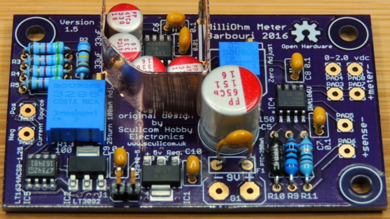
The finished project not only looks good, but is able to measure up to 2Ω with a resolution of 0.0001Ω (that’s 0.1mΩ). The project is originally designed by [Louis] from [Scullcom Hobby Electronics] and [barbouri]’s second iteration adds an improved board layout to the original project.
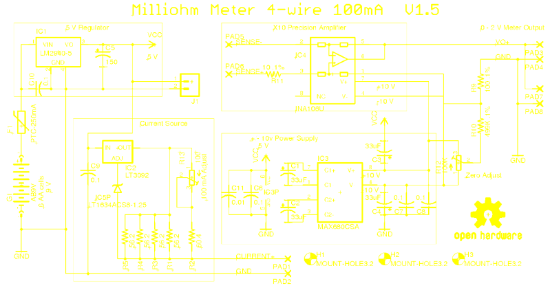
The schematic is essentially four well defined blocks. A 5 V linear LDO regulator powers the whole circuit. It receives power from a bank of six AA batteries, with a polyfuse in series for over-current protection. A switching regulator, or power derived from a utility supply may affect the stability of the current source. The constant current source is built around a LT3092 [pdf] — a 200 mA two-terminal programmable current source, adjusted to provide 100 mA output. Its accuracy is further improved by using a LT1634 [pdf] Micropower Precision Shunt Voltage Reference. This section also requires precision, low drift resistors to set the output current. [barbouri] spent time measuring a batch of resistors, checking their values over two different temperatures, and then picking the ones which showed the lowest drift. All of this effort translates in to keeping the current source as stable as possible.
When the 100 mA current passes through a 0.1 Ω resistor, the voltage across the resistor will be 0.01 V. Obviously, this needs to be amplified by a factor of x10 to provide the correct resistance reading on the voltmeter. This is done by the INA106 [pdf] — a precision differential amplifier with laser trimmed resistors. The dual power supply for the INA106 is derived using the MAX680 [pdf] — a dual charge-pump voltage converter that provides ±10 V outputs from a +5 V input.
On his blog post, [barbouri] shares all of the design files, including a face plate layout which will fit a standard Hammond enclosure. [Louis], the original designer, does an excellent job of explaining how the circuit functions, and follows it up with another video to walk through the updated version built around [barbouri]’s board.


A very handy tool! Add a sharp pair of kelvin probes and a speaker that plays a note proportional to resistance (and a headphone jack, to be polite to those sharing your lab!) and you’ve got the best tool for finding short circuits I’ve ever come across.
240 VAC is an excellent tool for finding and removing them simultaneously.
That’s like my saying: I have never seen a faulty TRIAC. but I often see the three legs left behind.
+1 for a RL LOL.
That’s a good one.. :)
I just had a Hackaday flashback.
kek.
If you think about their apliacation that’s very much a reality!
Unless of course if you use the hockey puck variant…
Pretty sure those would…liberate…themselves from the fixture as well :D
240VAC is also an excellent tool for eliminating intermittent faults.
We had to destroy the village in order to save it.
I have done that at time. If you spend an hour looking for an active load that is bringing down a power rail with a soft supply then you have wasted enough time so you remove the soft supply and connect it directly to mains and the problem will ‘self identify’ with a pop and a wisp of magic smoke.
HAHAHAHAAA. NO
Also see a rougher, readier, handy solution for short tracing: http://jaanus.tech-thing.org/half-ohm/half-ohm-milliohm-adapter/
I bought a GenRad Bughound a couple decades ago at an auction for $2.
Nice for troubleshooting short circuits, the resistance drops the closer you get to the short.
Each time I see a milliohm meter it makes me feel bad, ’cause it reminds me of this microohm meter that is waiting for years now in my bucket list: http://www.analog.com/media/en/technical-documentation/application-notes/AN-306.pdf
:o(
Excellent project and documentation. I especially like that it has a *real* schematic instead of a graphical net-list.
I am still using an ESR/Low Ohms meter I made in the 80’s. I see cheap ones on ebay now.
I’m glad I’m not the only one that thinks that those net lists suck when used in place of a proper schematic.
Both have their place, right? A good netlist can undo a scrambled rat’s nest of this-wire-crosses-that-wire when they all have logical names and etc. For a breakout board, for instance, I just want to know where MISO and MOSI go and don’t need to see the wires.
OTOH: analog circuits written out in the named-net style really don’t work for me. I need to see the wires, because I see sub-units (oh, that’s just a current mirror) in the shapes. Horses for courses. It’s about making the document readable.
And this one is absolutely beautiful — I actually remarked on that as I was editing the piece. Glad to see some other folks thought so too.
From a maintenance point of view, a net-list is close to useless. Imagine that you have *something* loading down a signal/bus/power rail. With a net-list you have to sight every connection point (net-list item) to do a quick mental comparison to see if it may be a cause of the fault condition.
When *all* the connection points to a specific circuit element are clearly displayed then it is quite clear which other elements of the circuit have the potential to cause the fault condition.
I realise to all the electronics experts out there this may seem a stupid question, so please be polite if it is. In a circuit diagram, is there any difference between the symbol for a capacitor drawn as two parallel lines, which is the way I was taught it, and the symbol used here, where one of the lines is curved away from the other at the edges?
The symbol with a curved line is typically a symbol for a polarized cap, where that curved line was one of the poles. IIRC those are just differences in US/EU symbols, I don’t remember which is which though.
The curved line denotes the negative side of a polarized capacitor. Usually an electrolytic, which you’ll mostly find for larger capacitances (>1 µF); its polarity must be respected, otherwise it gets damaged.
The “two parallel lines” symbol is used for an unpolarized capacitor, e.g. ceramic or film type; it can be polarized either way. Usually, these capacitances range from pF values to single µF’s, as it becomes difficult (but not impossible) to manufacture much higher capacitance values.
http://www.learnabout-electronics.org/ac_theory/images/capacitor-symbols.gif
http://www.micro-tronik.com/automotive/repair-basics/electronic-basics/images/TYPEs_OF_CAPACITORS_imageid_159.jpg
https://i.stack.imgur.com/A16tI.gif
As you can see, there are a lot of confusing and non-standard symbols for capacitors, and they have evolved over time.
Generally, polarized capacitors (e.g. electrolytics or tantalums) have a “+” on the schematic, in additon to a symbol that emphasizes these being “polar”. I particularly like the Japanese symbol with the hash marks between the plates. Europe often uses rectangles with one blackened. Americans usually use two parallel lines with only the “+” sign. The curved line is seen as well.
However, for NON-polar capacitors, if the schematic shows a straight line and a curved like, the curved side was an indicator for the outside foil (for example on a rolled mylar capactor). You see them more often in old-time vacuum tube radio or TV circuits.
On the physical capacitor itself the “outside” lead had a bar next to it. In the schematic the outside lead was often connected to ground to provide additional shielding to the signal on the other lead.
Thanks to all, particularly Ben Thar here. I am a European, so the electrolytic capacitor symbol I am used to is the one with one black and one white plate. I had no idea there was a different symbol for this in America.
I’ve always seen all sorts of symbols for things. I wouldn’t have guessed it was a US vs Europe thing. How does one get exposed to ‘US’ symbols or ‘UK’ symbols but not the other. Even before the internet it’s not like books weren’t regularly shipped across the ocean!
That being said, I like the US symbols better. Is it because I am from the US? Maybe. But.. try to draw them with a pen or pencil and tell me that symbols composed of only thin lines aren’t superior to ones that have thick areas which must be colored in. Come on, this Is why we don’t teach our children to write with fancy script like something out of a medieval book. It always surprises me that people even come up with symbols that contain thick parts since the invention of sharp-pointed writing utensils. Why do people hate themselves so much they have to create extra work? Now the resistor symbols… ok that one is a wash.
if you build this, note the BOM lists an incorrect part for R10. It should be 499K ohm not 499 ohm. This is per the schematic and the ina106 datasheet application note. This is an acceptable part for R10. https://www.digikey.com/product-detail/en/te-connectivity-passive-product/YR1B499KCC/A105891CT-ND/