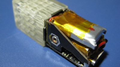
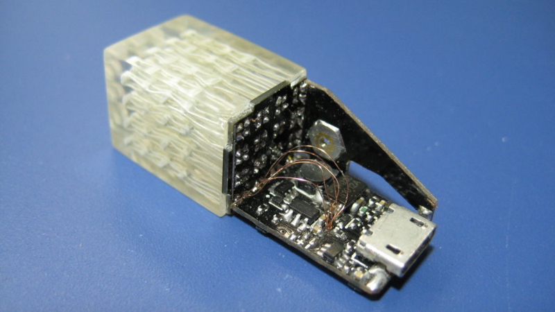
There’s a new challenger on the block for the title of the “Worlds Smallest 4x4x4 RGB LED Cube“. At 13x13x36 mm, [nqtronix]’s Cube Pendant is significantly smaller than [HariFun’s] version, which measures in at about 17x17x17 mm just for the cube, plus the external electronics. It took about a year for [nqtronix] to claim this spot, and from reading the comments section, it seems [HariFun] isn’t complaining. The Cube Pendant is small enough to be used as a key fob, and [nqtronix] has managed to really cram a lot of electronics in it.
The LED’s used are 0606 RGB’s which are 1.6mm square, although he did consider using 0404’s before scrubbing the idea. There’s many ways of driving 192 IO’s, but in this case, Charlieplexing seemed like the best solution, requiring 16 IO’s. Unlike [HariFun]’s build, this one is fully integrated, with micro-controller, battery and everything else wrapped up in a case made entirely from PCB — inspired by [Voja Antonic]’s FR4 enclosure technique, and the LED array is embedded in clear resin.
 Along the way, he’s had to resort to several hacks to bring it to fruition. For starters, he’s used the ATmega328BP [pdf], instead of the more usual ATmega328P, giving him extra IO’s to play with. And since Charlieplexing works better at higher voltages, he’s using a boost converter to provide +5.5V — the max. limit for the ATmega — to drive the cube. The LiPo charger has a slightly unusual P-MOSFET switching section to switch between USB input and LiPo without causing too much of a voltage drop. There’s a few parts to help detect low voltage, but his code doesn’t yet use this feature. He’s also thrown in an accelerometer in to the mix to respond to taps, double taps and shakes, but this too is not yet implemented in code. Since he ran out of board space, the EEPROM is dead-bug soldered. And the push button is built from, well, pulling apart a regular push button and using its innards. He’s posted the DIPtrace board design files as well as the code on the Instructable, in case some one else wants to take a stab at replicating the cube. Although we must say that apart from being a soldering Ninja, you also need pretty good mechanical chops to build this tiny cube.


It’s cool but I find it weird that the author couldn’t even throw up a 10 second video.
Heh. How different folks are. I, for my part am delighted about the quality of the text (insight into design tradeoffs, etc.) and am overly happy that it’s not (as often) a video-only thing.
Horses for courses, I s’ppose :)
+1 The information when there is no video is usually far more detailed.
-1
In this day and age every person can make a small video for a project that is in fact based on the visual aspect.
I prefer reading and wouldn’t have watched the video anyway.
But what about the animations?
one of those journey more important than the destination guys I guess
Reason for no video is quite possibly end effect is total shit
Yeah, I wish there was a video, too.
But to get it done before the exam period started, I had to cut some features from the software, one of which was the graphics core :( It’s likely that there’ll be an update in a few month ;)
Agreed, I was wondering how well the effect works when so large a percentage of the empty space in the cube is now filled with the LED packaging, so a video would have been informative.
Still it is a neat little project and I imagine that more superficial humans would pay a lot to be able to dangle something like that off various parts of their anatomy.
It would just be blinkin’ lights anyway. I think when things get this small the LED’s package type starts getting in the way.
Very nice write up!
13*13*36mm = 6084mm³
17*17*17mm = 4913mm³
It’s not smaller.
Ah, mea culpa, “17*17*17mm plus electronics”
How to waste your time – God Level…
Nice one bro!
I was thinking maybe mount this in an old clear relay
This is just insane!!! :-)
For removing the bubbles out of the liquid epoxy, maybe put the entire thing on a (powerfull) loudspeaker with the appropriate signal? I know that they are something like vibration tables for stuff like this, but they are probably $$$, maybe a loudspeaker will do? Or a piezo-thing?? Or simply fix the entire thing to a vibrating sextoy? ;-)
@editors: Iirc you usually provide (provided?) the ALLSTEPS-link to instructables, please continue! http://www.instructables.com/id/LED-Cube-Pendant/?ALLSTEPS
/?ALLSTEPS seems to redirect to the normal “first step” page.
not here, referer problem maybe? try copy and paste to a new tab.
Vibrating the resin may probably make it worse. IIRC, the recommended method would be to use vacuum de-gassing to get rid of the entrapped air.
Another good technique, cheaper, and easier to get your hands on is pressure casting. The epoxy is poured and put into a pressure chamber and pumped to 30 to 40 psi and left to cure. An air compressor is easier to get hold of than a vacuum pump, and the canisters (pressure vessels) for both are *reasonably* similar.
At 30 to 40 psi, it is the same pressure as your car tyre and the bubbles are nearly squashed out of existence… higher pressures squash them smaller, but carry the risk of a nasty explosion if the pressure vessel is not rated.
They will be squeezed to about 1/3 their original size. The best bet is to vacuum degas to remove the large bubbles and then pressure cast to make the little ones even smaller.
I found that heat can also help by reducing the viscosity and increasing the volume so the bubbles float faster to the top, but it takes a slower curing material to keep from curing suddenly. At least it works great with epoxies.
okay, looks like i confound something…
Awesome project. Great build.
As an improvement, the LEDs can be spaced apart so that the central 4 LEDs can be seen. I guess that would take away the title of the smallest LED cube but it improves visibility of 3D patterns displayed on the cube
He’s soldered the LED’s at a 45 deg angle to improve visibility (from one side, at least).
Originally I planned on using 0404 LEDs and placed the stacks a resonable 2mm apart. Unfortunately my Chinese parts had only solder pads on the bottom, which are impossible to solder to wires, so I went with plan B ;)
Very well written article, I coundn’t have done it better!
Thanks Anool!
Nah bro, this is 100% legit, check out the instructables page for details on how I made it.
Nah bro, this is 100% legit, check out the instructables page for details on how I made it.
Where is the schematic of the led PCB? where are the connections to the ATmega? Why can’t we see the boards on the photos? Prove that it works by providing at least a photo with the leds lit and clear view of the pcbs.
This Blog post is just a summary of the project. The first link in this article takes you to the project on nstructable.com, or just click on my username. There’s about 20 pages worth of details about the build, including the schematic, PCB design files, BOM, full source code and more.
I did read everything. That’s why i am calling this a sham.
You only need to provide a clear photo of the cube lit while the board is assembled to prove me wrong.
Why don’t you?
Oh sorry, sure you’re right, I was just horribly confused.
>The LEDs are not even connected…
I thought the LED PCB is soldered to the edge, traces or wires connect it to the atmega. Can you please cirle the spot where the connection is brocken? You got plenty of pictures to choose from.
>”… the code is just random words.”
To me it seems like plain, boring C code with a few lines of assembler thrown in. Where are the random words, I can’t find them.
>”Where is the schematiic of the LED PCB”
Which schematic? Do you think I had one, I did that out of my head! There’s no way I could have designed a custom part and placed like 16 of them on a single sheet.
>Where are the connections to the atmega?
I don’t like wires, I use net ports instead. Works like magic.
>”Why can’t we see the boards on the photos?”
We? This is the first complaint about missing boards I’ve heard so far…
>”Prove …”
I don’t think so, why should I? To win an argument with a troll on the internet? You gotta be kidding me, I have waaay to much fun to end this :^)
I just can’t believe that this is an obvious fake and no one in HaD gives a shit.
I’m not going to argue with you, there is no point.
His code is partially in this image here
https://cdn.instructables.com/FU4/KHBT/IY4QKZBY/FU4KHBTIY4QKZBY.MEDIUM.jpg?width=614
If you don’t understand the C thats fine but to call it a sham is inane.
His code is partially visible in the image here:
https://cdn.instructables.com/FU4/KHBT/IY4QKZBY/FU4KHBTIY4QKZBY.MEDIUM.jpg?width=614
If you don’t understand C thats fine but to call it a sham is inane.
https://cdn.instructables.com/FH2/66VY/IY4QL7M6/FH266VYIY4QL7M6.LARGE.jpg
I do not believe this is connected to the board shown in the instructables. Sorry.
Did you read the whole post there and did it make you confident that it is as shown and works?