A few months ago, someone clued us in on a neat little programmable power supply from the usual Chinese retailers. The DPS5005 is a programmable power supply that takes power from a big AC to DC wall wart and turns it into a tiny bench-top power supply. You can pick one of these things up for about thirty bucks, so if you already have a sufficiently large AC to DC converter you can build a nice 250 Watt power supply on the cheap.
[Johan] picked up one of these tiny programmable power supplies. His overall impression was positive, but like so many cheap products on AliExpress, there wasn’t a whole lot of polish to the interface. Additionally, the DPS5005 lacked the ability to be controlled over a serial port or WiFi.
This programmable power supply is built around an STM32, with the programming pads exposed and labeled on the PCB. The changes [Johan] wanted to make were all in software, leading him to develop OpenDPS, a firmware replacement for the DPS5005.
To write his own firmware for this power supply, [Johan] first had to get his computer talking to the main chip controlling the power supply. That was quick work with an STLink programmer, however the readout protection for the microcontroller was set. That put an end to reverse engineering the firmware, but that really didn’t matter – he was only interested in what the microcontroller talked to. After some work, [Johan] managed to figure out how to interact with the buttons, current limiter, ADC goodies, and the TFT display. An application was written with a vastly improved UI, with support for an ESP8266 plugged into the UART pins.
Right now, [Johan] has a significantly better power supply that can be programmed over WiFi. All the code is available, and there’s even a guide for hacking one of these power supplies. This is fantastic work, and we could only be so lucky if a random Chinese factory takes note and puts this firmware into their production line.


Awesomesauce. I was looking to do exactly that. Thank you.
this! I got one of these, saw the crappy UI and tossed it in a box. Now I can dig it out and make it useful. Thank you!
Will be expecting the Doom port shortly. :-)
This!
I see they’ve cracked it on the STM32F4 series: https://github.com/floppes/stm32doom but didn’t find anything for the STM43F1x yet though…
Ordered. Thank you. (c:
I can’t see the value in these. If it were buck-boost instead of just buck then it would be useful.
I mean, who has a 50Volt wall wart (plug pack) lying around.
Most of the higher power PSU’s hiding under hacker benches are laptop PSU’s at 17-20Volt or PC PSU’s that max out at 12Volt.
There is also buck-boost version – DPH3205 http://www.ebay.com/itm/401240588355
Of course the SW could be different, but now with know-how of DPS power supply there is big chance to make port for this version too :)
SEE DISCLAIMER BELOW!!
Pffft, get 3x 19V PSUs of same brand/wattage, some beefy diodes and some 100V rated capacitors (2200uF worth should do, 850uF-solid but unlikely find).
Consult a qualified electrician before continuing (maybe lawer about local laws regards mains)
Break open the PSUs (Plebs call them “chargers”) and remove the ground off of two of the PSUs.
Remove any resistors bridging the high/low voltage sides (the 10Mohm ones if present) and any Y capacitors that bridge to safety-GND on the two leaving one unmodded PSU as your GND reference.
Wire the diodes so each positive of each PSU points at the positive of each 100V capacitor stage (not charged at 100v BTW!)
Get your “ground-reference PSU” and wire it’s positive out to the negative of the next modded PSU and then wire the the next modded PSU negative to the positive of the total pack:
+{}-+{}-+{}GND(Neg)
^[]=^[]=^[]GND
{} = capacitor bank (100V)
[] = Adapter
^ = Diodes
The GND configuration maybe of safety concern in some countries, Also playing with the 60+voltage possible in this config is in danger territory anyway (Consult your local laws!)
All the live (240/110V) should be parallel wired and same (But not shorted with Live) done to neutral.
This will pull a surge on the mains and temporarily trip some RCDs Just reset the tripper before the breaker in quick succession to beat the surge due to the primary filter capacitor(s) in each PSU Primaries.
Recap:
Check Law(er)/Consult qualified Electrician
keep one unmodded PSU, mod 2X PSU to remove GND loops.
Connect output in series, Connect primaries in parallel.
Smoke-test, If pass smoke-test, Profit????
.
.
DISCLAIMER:
I am not qualified as an electrician or a Lawer, In NO circumstance am I responsible for ANY outcome should it be of good outcome or serious outcome, not limited to but including: DEATH, INJURY, LOSSES OF ANY KIND, MISUSE, ETC. Despite being written to the best of my knowledge, the example configuration as shown above is given, including but not limited to any errors or mistakes contained within, if there are any: without ANY warranty or responsibility. HackADay are also automatically devoid of any such responsibilities or warranties as per stated above, they also reserve all other rights granted by their laws and are entitled to the governing laws granting HackADay and it’s staff protection from the consequences of this post. It is up to the reader to take the steps to seek external qualified help within their country / county / or otherwise intentionally seek their locally known qualified personnel regarding the safety and laws of their country/province of residence/experimentation.
Forgot:
Keep the opto-ioslators in circuit! They are needed for feedback and they won’t interfere when above PSU is made correctly
Opto-isolator == the 4-pin chip bridging the primary-secondary circuits together using light.
I don’t like breaking open power bricks as there glued together. You could string three double insulated bricks together without opening them as long as they are all above the current output and withing their wattage.
BUT don’t try this with anything that has an earth wire going into it.
I use a laptop power brick for my soldering iron and for a small drill so perhaps I can get a cheaper buck only model PSU reg and have up to 18 Volts or so.
What’s the goal/idea behind this?
48V PSUs are common in telecom and networking gear.
The pre-PSU or the master-PSU?
I fixed a pre-PSU at work for a customer:
it says 50v in and 48v,15v-0v-n15v,5v-0-n5v out stabalized PSU, but the 48v was a straight wire to the 50v input.
This was because this PSU was 5v-logic and 15v+- for the amplifiers and the neg5v logic for the phone-line control logic,
about as much as I could gather just looking at the PSU and from the phreaker/hacker philes I had when I was too young to know better.
Ignore my question above:
I just re-realized that different stations, although similar power requirements, have variations on how they are set up.
I used to work for a telco. I never saw a 48 Volt supply that was less than three rooms big.
Smaller ones (as in a few kW) are more common now that data centers are going HVDC for the servers themselves and the 48V is mostly used by the networking equipment.
Something like 3 kilowatt in 2 rack units. It was not even deep.
You can get a Dell EPS-470 PSU cheap on eBay. It is 48v 470w.
a) You can of course run those power supplies from lower voltage. This of course limits the maximum output voltage accordingly. Still very useful.
b) 48V switch-mode power supplies are cheap. I have a whole army of DPS modules and went with this type of power supply: https://www.aliexpress.com/item//32282038391.html or https://www.aliexpress.com/item//32623475074.html which cost around USD 25 including delivery!
Those are reasonably good build quality, load controlled fan and essentially the reference design for the switch-mode chip they use. There are larger models too. For my use a limit of 360W total is comfortably acceptable and I run up to 3 DPS modules from one of these.
Nice. I got a slightly different variant of these that I’m planning on putting in a small enclosure. I like it but the interface is pretty damn ugly. This looks better, not great, but better. It looks like CC isn’t included though which is a no go for my needs. Hopefully since it’s open, this will be remedied down the line.
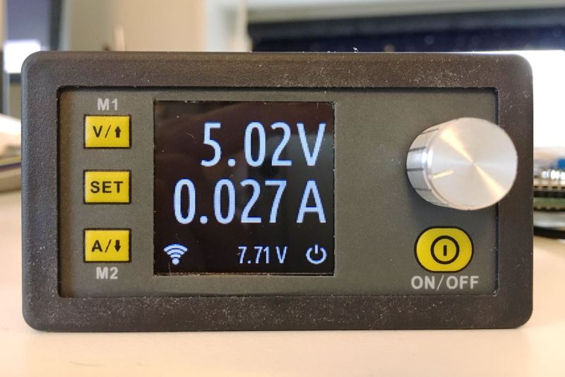
Actually, thinking about it some more. I prefer the original readout much better. There’s too little info on this one. A design update on the original display is what I would l want I think. Get rid of the terrible icons and change the colour of the rest of the display and I’d be happy.
I made a enclosure that you can 3D print if you want to use it. Works great for me!
http://www.thingiverse.com/thing:2040405
Thanks. The enclosure I’m planning will be a bit more involved as I’m adding some extra stuff I want (it will house a small PSU, on off switch and such), but thanks for the tip :)
I made a DIY enclosure for one here http://blog.nicolas.cx/blog/2016/05/19/low-cost-constant-currentconstant-voltage-power-supply worked out good.
Interesting that you went for a barrel jack. I’ve been going back and forth on that for a while now, I’ve bought both. I think in the end I’ll just add both so I have the option. I kinda like being able to attach bare wires, but the barrel jack is a lot more convenient for attaching other stuff.
I went with the barrel jack because it would make the enclosure smaller, and because I had lots of left over barrel jack pigtails from bad wall adapters. This made it easy to wire up a breadboard to the mini power supply. It also made it easy to supply power to the mini power supply as most wall adapters are barrel plug.
Wow, great work! I recently made a rackmount panel for this very power supply: http://imgur.com/a/VvthI
Your project here will be a substantial upgrade to my setup, I really appreciate you publishing this!
Im jealous. I like that you made a step level for it on your bench.
How are ripple/noise/step response on these guys? I’m not expecting miracles at their price point, just curious.
I want to know this too
I once plugged it into a Li-Po charging circuit, which charged the Li-Po (duh!) and powered an ESP-12E through an LDO. The ESP-12E had proper capacitors in place right on the module.
Result: ESP8266 kept restarting due to the ripple/noise/whatever magic. I removed the supply and and the ESP immediately sprung back to life. Cross confirmed by plugging the power supply back, again ESP restarts. Removed and plugged in USB from my computer and everything’s good.
This is when the Li-Po wasn’t even discharged much.
I wonder if I could cure that with some noise filtering on the output of the power supply. Definitely need to hit it with the scope some day!
I must be weird, I prefer the more detailed and color display then the newer single color display with less information on it. Good job regardless!
What display panel does it use?
I kind of need something with that aspect ratio and approx size.
Bummer! I have one of these and find it incredibly useful as a CC supply. Unfortunately, he hasn’t included CC mode in his firmware /sadface
Same here! If CC support was added I would hop on this in a heartbeat. Love these little DPS units.
Wondering how CC is implemented normally.
Given the inputs/output variables available (voltage in, voltage out, current) how does one make a constant current unit, do you keep an eye on the current and when it goes above your level, you temporarily cut off power or do you lower the voltage ?
Generally? Same as a voltage controller, swapping V and I: The regulator senses the output current (e.g. through a small series resistor) and let the voltage go up to the set point. The cheapest way to do it can be seen in the LM317 app notes (you put a second one in series and set Rsense=1.25v÷Imax). Of course you have to supply enough voltage for the load to draw the set current.
Regarding operation, think of it as a voltage limiter and a current limiter – current mode is letting the voltage go as high as needed but limiting the current.
Thanks
As cool as this is… I can’t think of an application for a serial or wifi-controlled power supply on my bench. I’ve gotten by for decades with home-built linear +/- 15v, 12v and 5v supplies, and only just last year I finally got a 0-18v/0-3A lab supply with variable voltage and current because it was cheap and broken and I fixed it.
But I remain open-minded; what clever uses do you folks have for a serial- or wifi-controlled power supply?
I don’t even have a bench supply anymore. Practically everything has a barrel jack now days and there are plug packs (wall warts) galore.
I have some switch mode modules as well.
I was tempted to build a linear bench supply using a re-wound multi-tapped Microwave Output Transformer (MOT) but I just don’t have a need for it.
Maybe I can re-wind the MOT as a 12 Volt car battery charger and use one of these modules, I just need something the size of a flux capacity for filtering at up to 65 Amps lol.
@rob, did you ever really have one? its by far the most instantly useful thing I have ever bought for working with electronics. when i ordered it I got a barrel set for it. I can power my f’king laptop from it. or more importantly when no led lights and no sound is made on the neighbors laptop, but he demolished the screen some how…. the current display can tell me if its on, if my button press is falling on a dead listner ic/mcu w/e for any misbehaving device with in its voltage and current output ability. The space it occupies (even considering set of barrels is far less than the huge box of walwarts that n\ow occupies the spare bedroom. speaking of space… the real evil about fucking walwarts is what the mix of ac and dc wiring and awkward huge plugs turns into behind your desk. and the physiccal spread of space the mains power bars take. One day I realized on a free standing shelving system I had a whole level dedicated to walwarts and power bar. Then while visiting my parents I spied a like 2003, switch mode 14.2v 20amp supply from when i was into ham radio. cool thing about 2017 is that just about everything plugged in has another internal DC-dc switcher or an ldo with a decent range (thats only one old 8port gig-e switch in my case..its from 09ish). I made a distribution board with hobby xc-30 connectors I keep stocked. it now powers my desk ip phone. router, 2x 8port smart switches, step up to inject 48v poe for a pi cam on front door, a component to hdmi converter for my old wii and a usb hub which powers my chrome cast /is there for phone charging as well. The space savings is huge and even running all that, it can still drive the dc motors in your moms vibe to tooth chipping speeds. …or just like cc power a cree led. im gonna argue that if you like walwarts over a bench supply or even over the effort of making a distribution board …you might be crazy
Do you have any pictures, id be really interested to see your setup – specially the distribution side.
Im always looking for ideas to make my setup nicer/simpler.
I have had several bench power supplies though I have never bought one.
Making your first bench supply was more or less a right of passage back then.
My first from (vague) memory was a variable 30V @ 1.5A (max) that had overload protection but no current limit.
The second was more interesting. In the main box was two 15V 4A center tapped transformers, one or two rectifiers, two large capacitors and a 3 way 4 pol switch. The switch selected the transformer mode: Parallel Single rail (15V @ 8A), Series Single rail (30V @ 4A) and Split rail (+/- 15V @ 4A).
On top of the box was a pair of 2 banana sockets. Within each pair, the banana sockets were places a precise distance apart to suite dual pin banana plugs like this –
http://www.smp-ltd.com/products/295_1306940784_Plug.jpg
I used a nikko pen (sharpie) to paint the negative side black.
This was the standard for power in my workshop.
Into the dual banana sockets I could plug in a lead to use unregulated voltage.
The overall pin spacing of the banana sockets was so that two small standard sized project boxes would fit side to side and plug into one dual socket or one larger standard sized project box (twice the width) could plug into both dual sockets.
The smaller sized boxes contained single rail regulators + or – 15V, + or – 12V, + or – 9V, + or – 5V, + or – variable voltage with current limit. Any box being + or – could go on the left(-) or right(+).
I also had an extension lead to plug into the main box and have the regulator box at the other end so there were no long regulated wires to cause problems. ie the regulator is close to the load.
The concept was to have one box for the bulky and more expensive parts and just make new regulators as needed.
That bench supply lasted me 35 years until someone “borrowed” it permanently.
I haven’t needed a variable supply since. Now everything is : 5V also covers 3v3 devices with in built regulation, 12V for steppers or 5V devices that have inbuilt regulation, 19V for laptops and my soldering iron or 24V for steppers.
So I have a 5V 3A switching wallwart for things that don’t run off a USB port. a 12V 2A switching wallwart for anything 12V, a 19V 9.5A switching brick to run laptops when repairing, a 19V 4A switching brick for my soldering iron and I use dedicated 24V and 5V switching modules for things that have steppers. Then in an emergency there are always some PC power supplies lying around.
I have been tempted to build another bench supply but there just hasn’t been a compelling need.
power supplies that can be controlled over the wire or wirelessly find use in device characterization. Look at the typical transistor / IC datasheet – there are graphs of a particular parameter (e.g noise figure) vs. voltage / current.
Yeah, kind of the same to me. Probably why my programmable power supply is in the works for 10 or so years. And my most used one is a tiny device with 7805, 7812 and LM317.
My favorite thing about programmable power supplies is that a lot of them let you make fatal mistakes such as changing from 5V to 15V with a single operation. Here’s an example https://youtu.be/mZD4HnwY2-8?t=569
That Video looked like a software Constant-current failure more than anything.
My cheap analog bench PSU can do CC and CV without any hiccups whatsoever,
but the one at work jumps from CC to 9A (Not even rated for this) and also sometimes jumps to 30V when set to say 5V and the CC limit is hit too suddenly (BANG! out goes the magic smoke!)
I think in the video the current limit was left at max (5A) and then the guy edited the first digit of the voltage instead of the third.
My ($100 ebay surplus) Instek dual output bench psu is literally in constant use – I don’t think I’ve turned it off in a couple of months now – has old skool pots for CC/CV and 7-seg LEDs and I’ve never edited the wrong digit because you can’t :-) I lived without a bench psu for years and then when I got one it was a revelation
@Dr.Tune i think the point here was the limited use of a serial/wifi control of a power supply, not that a bench one is not needed.
this accident is due to alarm clock/VCR user interface
” I can’t think of an application for a serial or wifi-controlled power supply on my bench.”
Off the top of my head:
1) Automated device characterization/power cycling.
2) Remote monitoring.
3) Power control in inaccessible locations.
The other thing I think you’re missing is that with smarts in a power supply, it doesn’t have to be a *passively* controlled device. It can actively push information and warn other devices. Imagine you have a workbench setup running in a shed off batteries. Suppose it’s streaming its stats via MQTT or something like that – you could easily set something up to warn you if charge is running out, so you could turn off any downstream devices.
Would also be handy to implement a safe shutdown command, where the supply sent out a warning to powered devices that the input power was about to shut off.
Yeah, but non of those are that desired in a hobby / home lab. Of course now that an ESP cost $2 I would rather have wifi control than not. It is even cheaper than adding an optically isolated usb port and cable.
I never felt the need to try characterizing any device and that’s unlikely to change for at least a couple dozen of my next lives. I can see how some people might want to of course, and this PSU should be much help with that for all three of them. I’ll just go on not having (or needing) any bench PSU for now. Plenty of USB PSUs out there, some of them are even quite decent…
The next best thing about this new firmware would be to upgrade to a larger 320×240 ILI9431 LCD (same controller).
nah, it would be adding front Linear stage
To add a linear stage you don’t need to change the firmware, you need to change the hardware. You add a linear regulator controlled by the DAC that was controlling the switching regulator. Then you add another circuit which controls the switching regulator so that its output is x higher than the output of the linear stage.
precisely, this would eliminate all (most?) drawbacks of switching supply – capacitor bank at the front limiting usefulness of OC, and pulsating output(unless its running at MHz instead of usual KHz crap).
bigger display on the other hand is redundant when you have wifi, open ESP generated webpage on your desktop and you have 24″ 4K display.
Not really, it is more complicated.
A switching regulator operates at frequencies at which a linear regulator is not that good of a filter. It may work well at 100/120 Hz, but not that well at 120kHz. Easily, you would add a filter in between.
I do support the idea of any instrument having a web interface. With basic things you have on a desktop such as zooming and window resizing you can easily make a simple display that gives you a control panel view of whatever you are doing with multiple instruments.
This predates the ESP8266 and modern routers can do more, but principles are stil valid http://www.electrobob.com/web-interfaces/
I looked into this, there seems no way to take apart the smaller version of the supply without destroying it. (I don’t have a hot air station). There are 2 16 pin headers connecting the 2 boards, and the important parts to access are in between the boards.
All the notes I’ve seen for the DPS5005 state a Max input voltage of 55v. Does anyone know if it will handle 60v from an typical eBay DC 60V 5A switch mode PS? If not, what’s the best option to feed it 55v from a cheapish SMPS, as I don’t see any obvious 55v models.
If it’s from China and they say it’s good for 55 Volts then it’s good for 54.999 Volts but only when brand new. Id’ get a 48 Volt supply.
I run these at 50V out and they work just fine:
http://hackaday.com/2017/03/07/open-source-firmware-for-a-cheap-programmable-power-supply/#comment-3439769
I didn’t check if they can be adjusted higher, if you want to be really sure you can just buy the next higher voltage version and turn it down. The adjustment potentiometer tends to go quite far down off the nominal voltage. I wouldn’t crank it up much beyond nominal, as the components are limited, especially capacitors.
I also tend to derate my supplies to offset “optimistic” chinese advertising. Usually I try not to exceed 50% nominal load.
Thanks for the suggestions! I purchased a 48v 10a SMPS, I didnt realize it had an adjustment pot till I looked at the images closer. That should do nicely.
https://github .com/kanflo/opendps/