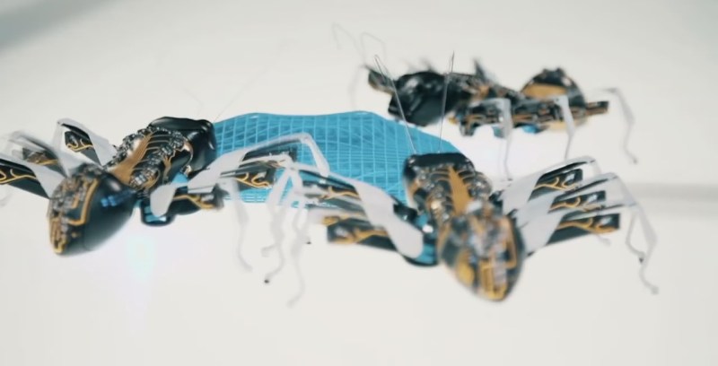
[FESTO] keeps coming up with new tricks that make us both envious and inspired. Take their bionicANTs for example. Watching a group of them cooperate to move objects around looks so real that you’re instantly reminded of the pests crawling across your floor, but looking at them up close they’re a treasure trove of ideas for your next robot project.
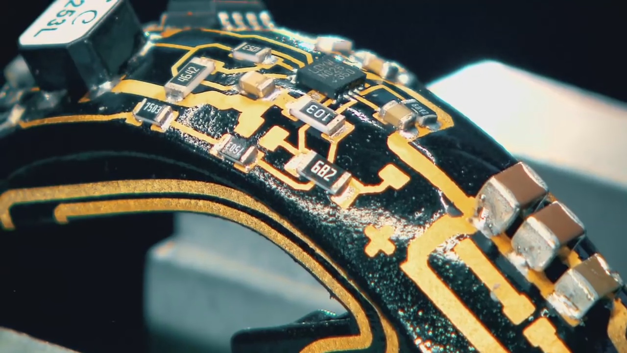
The exoskeleton is 3D printed but they then use the outer surface of that exoskeleton as a circuit board for much of the circuitry. The wiring is “painted on” using a 3D MID (Molded Interconnect Device) process. While FESTO didn’t give specifics about their process, a little research shows that 3D MID involves the 3D printed object being made of a special non-conductive metal material, a laser then “drawing” the traces in the material, and then dipping the object in various baths to apply copper, nickel and gold layers. We mortal hackers may not have the equipment for doing this ourselves in our workshops but seeing the beautiful result should be inspiration enough to get creative with our copper tape on the outer surfaces of our 3D printed, CNC’d, or hand-carved parts.
We also like how they took a the mouse sensor from under a regular computer mouse and attached it to the ant’s underside, pointing down for precision dead reckoning. For the legs they used three piezo bending transducers. However, these give a deflection of only 1.5mm in both directions, not enough for walking. They increase this to over 10mm with the addition of a plastic hinge, another idea to keep in mind when building that next tiny robot. And there are more ideas to be taken advantage of in their ants, which you can see being built in the video below.
But this isn’t the only time FESTO’s creative ingenuity has been shown here on Hackaday. Check out their bionic kangaroo that actually hops around, their robotic bird that has to be the most life-like one we’ve see yet, or how about their flying manta ray blimp instead.


those are not ants, those are giants lol
All fun and games until one of those SMD pops off.
Add zappers like the bugs in Minority Report.
Before that was killer acid robots in runaway, tom sellek
If it’s got leads we can kill it.
Swarm robots and their logic are a constant fascination that seems stuck in the bucket of the hype cycle somewhere between “latest thing” and “everyday use”. Googling “low cost swarm robotics” will get you a bunch of useful links (as below) if you’d care to try your own. Kiva Robotics with Amazon distribution centers and Air Liquide’s distribution network and a few others have made a good case for this but general industrial implementation is mostly a long way off. The problem is not with the technology itself but the ossified, cloistered and resource-starved thinking of production and distribution engineering in fields where it would do the most good.
http://www.math.ucla.edu/~bertozzi/papers/PheenoICRA2016.pdf
“the ossified, cloistered and resource-starved thinking of production and distribution engineering in fields”
That hasn’t been my experience, but I don’t pretend to have seen everything. The engineering departments I’ve worked in/with were all open minded enough to try out any promising new technology that seemed to have potential. The biggest road blocks I saw were the bean counters who didn’t want to spend any money on improvements if the current system was still functional.
What have Amazon’s Kiva robots to do with swarm behavior?
One thing I can think of is planting seeds. You will be amazed how techno farming has become.
interesting article
Right now there’s not really an advantage of this way of placing components because polyimide (kapton) would still result in space savings due to smaller traces being possible. But it looks nice, and things may become smaller in the future.
That Golden ExoPCB looks amazing!
Dat Spine!!! So golden! :)
I have tried and failed epic with soldering such metal-on-plastic, I just end up with a plastic blob on the end of the smoldering* iron. So much respect to those whom did so here… unless the to-be-soldered areas were reinforced with and/or used high temperature resistant plastics like the usual glass reinforced resin PCBs.
Random, somewhat relevant info for entertainment:
At 5:42 in the video, it appears like he has no anti-static connection, just a wrist-band. This would be fine in assumption that his is the replica of the other devices and a known good code is ran first to determine the sanity of the machine (Static/dry-joint/defect/etc, And I believe he is making a replica anyway).
Only First-prototype batches, High-performance ICs and production-line is where static protection is paramount to ensure static charge is not the cause of any failure. Repair, especially of anything containing lethal voltage potentials (of both sort) is where it is better not to have anti-static wristbands: Who here will volunteer to unhook a capacitor bank in a freshly smoke-tested (as in went BANG!) HDD-Degausser with anti-static prioritized over personal safety to try prove me wrong?
Honestly, I never wear a wrist strap, and I really can’t think of any time I have damaged a prototype or one has just stopped working. Generally, I am only building things that need to work for a while to prove a concept.
On another note regarding voltage, Piezo actuators often require 100 V to achieve large position changes. Maybe that’s another reason he’s not wearing a strap.
This sounds like how ICs are made: start with a bare substrate, then successively mask out layers of material to add to make the traces. This is the opposite of how PCBs are normally made: start with a substrate with the conductor bonded to it, etch/carve away where you don’t want it to conduct.
I wonder if there are paints/resins/epoxies conductive enough for screen-printing PCB traces? It would be interesting to make a board with multiple layers of traces printed on one side (with insulating layers printed in between, of course).
Based on experiments with screen printing conductive ink, you’d have to do it several times to get the resistance down to anything useful, except sensing, or maybe an LED. The problem would be registration.
The ants are not looking like being “offroad capable”… so why do they have legs?
If they only can operate on a perfect plane, wheels would have been the easier choice…
It’s just the beginning of the invention of skynet….
Remember (albeit not quite skynet related): Daleks were defeatable by just a set of stairs… Until they could levitate.
Some cooperating Daleks would have made a good commercial too!
\o/
I think it would be far more accurate to write that they use their exoskeleton as a PCB.
indeed. And although they claim in the video that the outer body has the most surface area and is therefore perfectly suited for placing components… yeah right. The real reason it that it looks cool. From a technical point of view it is ludicrous to design and expose components in this way, difficult to assemble, susceptible to RF noise, easily damaged, blablabla and all that trouble in making it because the case could not fit a PCB?!?! Sure… why not make the whole body a few % bigger in order to fit a PCB of a few tenths of mm thick. The only benefit I see is that this method of design creates the traces/wires to power the legs and I guess that because they’ve had the wires on the body anyway that they decided to add components also and before they knew it the outer body was a PCB. But then again… it would not be the first time I would be wrong.
Anyway… it looks really really cool!
It seems to work and the technology behind it to make it walk is very interesting in many ways. Then it can also navigate and find a target… wow! If this project was to enter a robotic contest, I’m sure it will win on it’s looks alone.
Works well for prototyping. For a real “production” I’d say print thin body parts then print the circuitry on the inside
Am I the only one now thinking of that novel “The Hacker and the Ants” by Rudy Rucker?
That said this is interesting to look at, especially those conductive traces they put on the body to attach the SMD components to.
Though this looks more like some sort of art project then anything else.
Nope, you weren’t the only one.
Bad solder joint on the three ceramic chip capacitor terminals in picture number two, lower right corner ;-)
Reminds me a lot of these old guys
http://www.ai.mit.edu/projects/hannibal/
Attilla really inspired me. I saw Attilla on the cover of Scientific American, in a hospital waiting room back in 1991. In one singular moment, my concept of robot went from Doctor Who’s K9, to THAT exquisite electromechanical beauty! I never had the resources to make anything quite nearly as advanced, but I did end up getting into simple walking robots, and even got to see Genghis and Hannibal at an exhibit at the Science Museum of Minnesota!
http://richfiles.solarbotics.net/robots/SpyderClosed.jpg
This is the extent of what I was able to build, with my limited tools and funds of the time (1999). The date also explains why the photo was taken with a potato. :P
You got further than I did, I barely got past the design stage. Though my plan was probably too ambitious, I devised a microcontroller based neural network to control mine.
I think I saw the MIT insects in a popular science magazine around 1990 or so.
I’ve been desperately wanting to revisit my old robotics using newer construction techniques and newer tech. Above all else though, I’ve truly wanted to create a more capable robot than that one. The design you see above is physically able to turn and reverse and such, by way of the leg geometry… It just was never wired to do anything but blindly walk forward. The robot has 4 PC boards, divided into three sections. The “T” shaped assembly of two boards up front is the “brain”. It consists of 16 neurons, arranged as a central ring, and 4 branches. Each branch drives a single leg. a bundle of wires jumpers the ‘brain” over to the signal conditioning board, which is just some 74xx logic to prevent the motor driver board from getting any illegal commands. The final board is a motor driver board with 8 transistor based H-bridge drivers.
My design always expected a fifth board, but it never got made. there were some configuration jumpers on the signal conditioning board that allowed it to relinquish control to a sensor board. That would have selectively altered the pattern sequencing to allow things like reversing and turning. Part of me wants to finish it, and another part of me realizes the robots has been the way it is for nearly two decades. Why change it, when I’m so interested in starting a new one someday?
They look amazing, but the only reason for doing that is “art”. I guess you could dip them in silicone rubber to protect them while allow the details remain visible. There is a crystal clear blend available.
I’ve always liked Festo’s bio-inspired robotics projects.
We need an article about how youtube videos won’t play on any browser except chrome because google is being an ass to everyone in there efforts to kill abobe flash.
Works on firefox and I don’t even have flash installed
Works better on Palemoon and other browsers because Failfox wants FalseAudio.
Unless FalseAudio is stable on everybody’s machines around here, then I guess the Firefox experience would be an awesome silent movie with audio still playing when you thought the machine has finally switched off (Satiric/Sarcastic rant at PulseAudio latencies)
This is another circuit on the outside robot
http://home.ctlnet.com/~minimechadon/minimechadon.htm
thanks for that link, I remember seeing that on a cover of a magazine a loooong time ago as a kid. I was amazed.
ahh hackaday where a 2 year link constitutes NEWS. Thanks for keeping us up to date guys LOL