Economies of scale and mass production bring us tons of stuff for not much money. And sometimes, that stuff is hackable. Case in point: the $5 Sonoff WiFi Smart Switch has an ESP8266 inside but the firmware isn’t very flexible. The device is equipped with the bare minimum 1 MB of SPI flash memory. Even worse, it doesn’t have the I2C ports extra pins exposed so that you can’t just connect up your own sensors and make them much more than just a switch. But that’s why we have soldering irons, right?
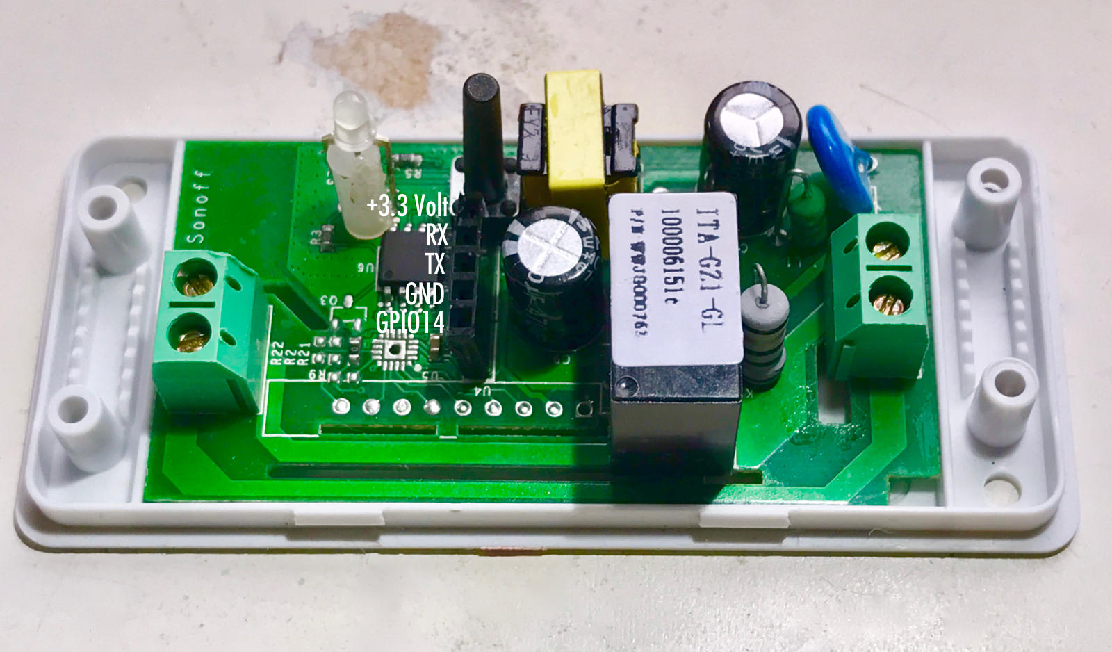 [Jack] fixed his, and documented the procedure. He starts off by soldering a female header to the board so that he can upload his own firmware. (Do not do this when it’s plugged into the wall, you could get electrocuted. Supply your own 3.3 V.) Next, he desolders the flash memory and replaces it with a roomy 4 MB chip, because he might want to upgrade the firmware over the air, or just run some really, really big code. So far, so good. He’s got a better version of the same thing.
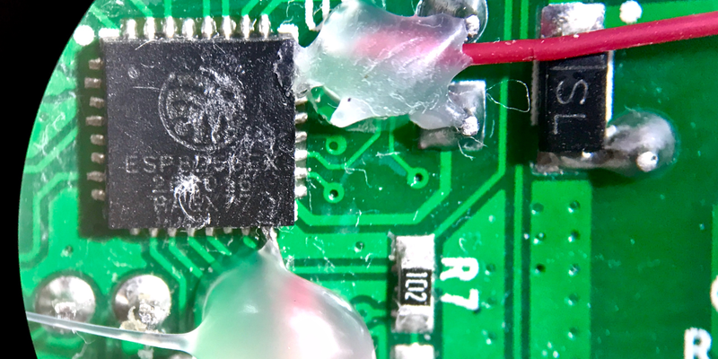
But breaking out the ESP8266’s I2C pins the pins that ESPEasy uses for software-emulated I2C turns this little “switch” into something much more useful — a wall-powered IoT sensor node in a sweet little package, with a switch attached. It’s just a matter of tacking two wires onto the incredibly tiny pins of the ESP8266 package. The good news is that the I2C pins are on the edge of the package, but you’re going to want your fine-tipped iron and some magnification regardless.
That’s it. Flash in a better firmware, connect up whatever I2C devices you’d like, and you’ve got a very capable addition to your home automation family for just a few bucks. Just for completeness, here’s the warning again: this device uses a non-isolated power supply, so if the neutral in your wall isn’t neutral, you can get shocked. And stay tuned for a full-length article on transformerless power supplies, coming up!


$5 Sonoff WiFi Smart Switch
Reality
$12
Settling
$24
$5 ‘~’
WTF are you on about? Or maybe just what are you on?
%Guy puts mustard on his fires
“WTF are you on about? Or maybe just what are you on?”
Probably the shipping charges from Itead which can quickly get quite high.
In call faireness they are going for as much as £14.99 + £1.59 delivery on amazon in the uk. But theirs many cheeper ways to obtain esp magic in the uk, like ebay, banggood or even direct if your looking for 100 min order.
To be fair, it’s $7: https://www.aliexpress.com/item/Sonoff-Remote-Control-WIFI-Switch-Universal-Module-Timer-ABS-Wireless-switch-For-iphone-Android/32777453503.html
Currently $4.85 direct from itead (the designers) https://www.itead.cc/smart-home/sonoff-wifi-wireless-switch.html
plus shipping. Making it the same.
A better choice….
http://www.electrodragon.com/product/wifi-iot-relay-board-spdt-based-esp8266/
http://www.electrodragon.com/product/wifi-iot-relay-board-vdc-based-esp8266/
I’t is really around $5 USD. Usually the sellers sells 3 things: *1) WiFI version, *2) 433 Mhz version, *3) 433Mhz remote control http://s.click.aliexpress.com/e/aEEE23N. Can’t find one with free shipping (it’s almost $1.5 USD)
Use Banggood.com
$5.68 with shipping
http://www.banggood.com/DIY-Wi-Fi-Wireless-Switch-For-Smart-Home-With-ABS-Shell-p-1019971.html?p=MT1805165590201304RP
The bad news is that it’s all unnecessary, because the ESP8266 doesn’t have any “i2c pins” — it only has software i2c, and you can use any two pins for it, in particular, the ones that are already exposed. You can even use one or both of the UART pins — for instance, use the RX pin if you are not going to be sending anything to it. The other i2c pin may be GPIO0, which is also broken out.
The guy used GPIO4 and GPIO5 to conform to the informal standard, and apparently didn’t know about multi-purpose pin trick. BTW, thank you for the tip!
I’m well aware of that the esp8266 doesn’t have hardware I2C (it’s mentioned in the article), but the only accessible extra GPIO pin is GPIO14. I needed that of a PIR sensor. Hence the adding of GPIO4 and 5.
Main safety looks ok, but is it?
As long as it’s in the box and switching small resistive loads, it should be.
I doubt it has any approvals from UL and the like.
It does appear to have a flyback SMPS with a transformer so it might be galvanically isolated if it has optocoupler feedback. But the transformer may not be insulated properly to pass a high-pot test.
And it’s not clear what the true safe load for the relay and terminal blocks and PCB traces will be, especially with a reactive load.
Purely out of curiosity, why does it matter if the power supply is isolated on a device where the only inputs and outputs are at mains power? It would seem to me that the isolation of the power supply would only matter if there was some way for the end user to come in contact with the low voltage. As it is, you would have to break a seal to touch any of the low voltage traces.
That’s true – a lot of devices like plug-in power meters, 433MHz remote control switches, and line-powered PIR motion switches don’t have any galvanic isolation at all, they often use capacitive-reactance transformerless power supplies.
That works well, and it is safe and cheap and easy. But if you take it apart and hack it you need to be careful! Connecting it to a PC or an oscilloscope while the AC line is connected could get you into trouble.
the vast majority of devices in this product line do have the logic nicely isloated from the mains power. The POW model (which measures energy usage) does not.
Wait, isnt esp8266 i2c just bitbanged? Theres no such hardware, so any already exposed pins could probably be used with less effort and a new library
Yeah, that is weird. Probably just a misdirected person, though.
He mentions this fact in his write-up:
“The processor doesn’t have hardware I2C support, so you can use two free pins to connect, but usually (and in ESPEasy), GPIO4 and GPIO5 are used for I2C connections. Here I have soldered a thin wire to pin 24, which is GPIO5(SCL).”
Oh, I read through it and the post 1) mentions lack of hacdware I2C 2) says that the most often used pins – GPIO 4 and 5 – were used, this makes sense.
Boo! Bad writeup Hackaday! Fix immediately!
(I’ve never used I2C on the ESPs. Sorry.)
How about CE-certification?
Sure it comes with the China Export symbol
https://www.itead.cc/wiki/File:CE_Certificate_for_Sonoff_Series.pdf
I just saw this other teardown earlier this day. It seems that some models have a 433MHz receiver.
http://www.chet.ie/?p=240
This is a great firmware to use this device with SmartThings (Home Automation kit for people who arent using HA/Domoticz). Shame it isnt open source, but still works very well in my experience and enables support for things like temperature sensors if you buy the right Sonoff.
OTA works just fine with the stock flash chip. I run a couple of Sonoffs with OTA and a MQTT library and still have some memory left, albeit not a lot.
I’m preparing for ESP Easy 2.0 ;-)
sonoff had a fire hazard recall on those internet of shit switches recently, so be warned
https://www.itead.cc/blog/sonoff-th16-and-pow-recall-notice
that was a different model
This firmware works well on these switches without needing to replace the flash
https://github.com/arendst/Sonoff-Tasmota/
It also supports a wide range of things hooked to the additional GPIOs
This firmware is growing into a general home automation for esp-8266 based devices as it’s gaining more options for more devices and more sensors.
I use Sonoff-Tasmota with 3 of the Sonoff-Basics, a Sonoff-Slamapher, and a Sonoff-Wifi Touch. It works great on all of them.
Why would you hack a board you can buy for under $4 out of a gizmo that sells for over $5 and does not have all the pins brought out on?
Because it has build-in SSR($2~), 3.3V AC-DC($1~), and decent enclosure(~$1).
it’s not a SSR, it’s a regular relay.
But you can get the ESP-8266 for <$2 each (including shipping), but then you need to add a power supply, relays, switches, enclosure, and terminals to connect the wires to
the sonoff devices are nice and cheap and don't need all those other things.
They're not for everyone, but there's no reason to attack someone who does want to use them.
Here, let me relay a message to you:
LOOK AT THE BOARD.
There’s tons of websites and videos on You tube regarding re-flashing the Sonoff and using such things as MQTT and Node-Red to create a nice dashboard but for me, I definitely prefer to use the boards by LinkNode or Link Sprite. The board I use is about the same price (sonoff is $12 Canadian on Banggood, LinkSprite is $12 on Amazon.ca).
It has 4 relays connected to GPIO pins 12,13,14,16 and the others can be used by soldering wires to the ESP. It’s better in every way other than not having a plastic enclosure.
The Linksprite has the full Esp8266-12 on board which is much easier to solder to. They also have a model that is just like an Uno if you want easier access to the pins.
Like the Sonoff, the PCB has voids cut between the high power sections to help prevent arcing.
Also, like the Sonoff the board doesn’t have onboard usb-serial but has the tx and rx pins and real easy to flash- just move 1 jumper. I can flash the awesome ESPEasy firmware just by running an exe and it takes less than 1 minute.
It works very nicely with Node-Red and Mosquitto MQTT running on a Pi 3
Here’s what it looks like:
http://www.instructables.com/id/DIY-Home-Automation-With-ESP8266-Linknode-R4-and-A/
No enclosure is a big drawback. But most important is that the stuff is usable WITHOUT any Cloud connection. That’s the main reason for me, why I look about hacking these.
Nice hack, i don’t think i could every reliably solder to those tiny pins. On a side note, were you partial to espeasy? I’m fairly certain that Theo Arends TASMOTA firmware allows you to use gpio 14 as well as the rx/tx uart pins for i2c via software.
yes it does
Besides Tasmota and ESPEasy, there is a great, very comprehensive firmware called ESPurna that supports all features of above firmwares; and supports many boards including Sonoff and ElectroDragon, with MQTT enabled and integrating Alexa, HA and Domoticz:
https://bitbucket.org/xoseperez/espurna
you may want to double check the “supports all features” claim :-)
With opensource software things can change rapidly, I’ve been watching both espurna and tasmota and I’ve seen a lot more activity on tasmota recently
@davidlang,
I will be glad to see all such FW beating out each other for the good of all :)
That is FOSS.
@davidelang
Sorry for your name typo.
Btw, ESPurna is still ahead.
A question from ignorance here – but why not use the I2C pins that are used to talk to the EEPROM? Just make sure your I2C devices are on a different address to the EEPROM, and use the easily accessible pins on the EEPROM….
what I2C EEPROM? SPI flash :P