For those of us whose interests lie in radio, encountering our first software defined radio must have universally seemed like a miracle. Here is a surprisingly simple device, essentially a clever mixer and a set of analogue-to-digital or digital-to-analogue converters, that can import all the complex and tricky-to-set-up parts of a traditional radio to a computer, in which all signal procession can be done using software.
When your curiosity gets the better of you and you start to peer into the workings of a software defined radio though, you encounter something you won’t have seen before in a traditional radio. There are two mixers fed by a two local oscillators on the same frequency but with a 90 degree phase shift, and in a receiver the resulting mixer products are fed into two separate ADCs. You encounter the letters I and Q in relation to these two signal paths, and wonder what on earth all that means.
What you have just seen is a quadrature mixer. Quadrature refers to anything mathematical that involves a quarter circle, in this case the 90 degree phase shift between the two local oscillators. This 90 degree phase shift has the property of revealing not only the frequency and amplitude information in the signal that you would be familiar with from a single mixer in a traditional radio, but also the phase information within it that the two 90 degree out of phase I (In phase) and Q (Quadrature) component signals preserve.
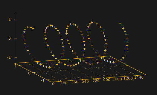
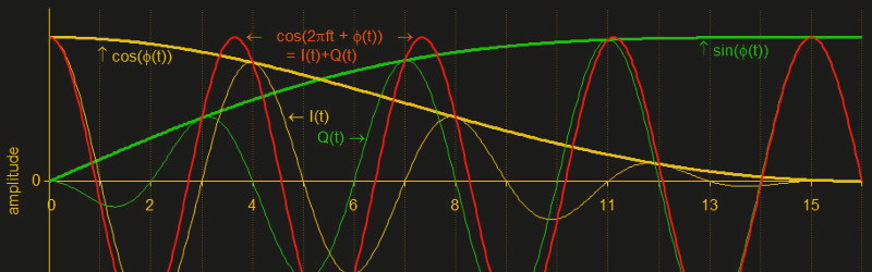
There is a significant amount of maths to be digested if you wish to fully get to the bottom of how this works, for which it is probably best to direct the curious to a more lengthy explanation. For a quick understanding though it is best to imagine the sine wave amplitude view of a signal that you might see on an oscilloscope as merely a 2D side view of a signal that is in fact a 3D spiral because it also has a phase component. If this side view of a spiral were your I component then a similar 2D view of the top of the spiral would be your Q component, the same signal but with a 90 degree phase difference. From these two I and Q signals can be reconstructed the whole of the original signal including its complex phase relationships, rather than simply the 2D amplitude view that you might see on an oscilloscope.
Happily this isn’t one of those things that exists only as a piece of theory in a text book, you can easily build a simple SDR receiver front end based on the quadrature mixer diagram above on your bench. If you are prepared to restrict the receiver’s bandwidth to that of your computer’s audio card, often in the 50 kHz range, you can use the left and right audio inputs as your I and Q respectively, and run one of the many SDR applications. Linrad is just one example.
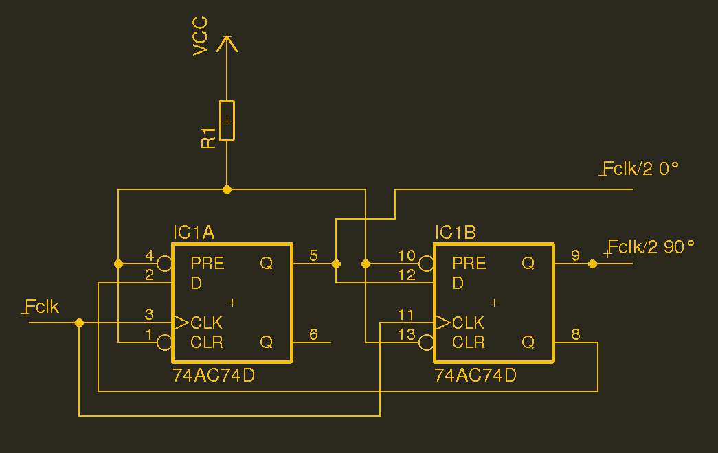
As to the hardware, the mixers and associated low pass filter can be extremely straightforward to build, for example you could try lifting this design using a CMOS analogue switch. And though you might imagine that creating the 90 degree phase shift would present a problem, in fact that too can be easily performed with a pair of flip-flops. Add in a logic level oscillator and it’s then possible to make a software defined radio front end almost entirely from logic chips, save for a couple of op-amps. It won’t perform much beyond the HF (shortwave) frequencies, but even if you only use it to look at your local AM broadcast stations it can still give you a hands-on understanding of SDR hardware.
It sometimes seems as though SDRs are magical black boxes surrounded in a cloud of marketing woo. And with the exception of the famous RTL chipset USB TV receivers they seem to attract a price to match the hype. But the reality is that from the hardware perspective they can be surprisingly simple. Why not break out a breadboard and hack yourself together a simple one!
Header image: Bob K [CC0].


Nice intro to SDR. And the RTL-SDR is definitely a recommended way to start playing with SDR. But I’d like to make the case for SDRs like Airspy and the SDRplay RSP family which also add optimised filtering and higher resolution Analog to digital Conversion together with some great software. Take a look at the RSP videos on https://www.youtube.com/c/SDRplayRSP
> There are two mixers fed by a two local oscillators
Benchoff isn’t the only one to make typos.
Yes. They like to stress presenting the project on it’s merits and it’s interest to the typical audience of HackaDay over typographical errors. Given that many of the grammar police who haunt forums are also bad about the same things, I think it’s a fair trade off.
But what do I know? I’ve only written five books…
But I feel I must add I DID offer to proof read for them. :D
presenting the project on _its_ merits
but you expected this, didn’t you? :P
You’re such a nitpicker ! :-)
And you are wasting my time by criticizing typos. I just overlooked them while reading (like a mental auto correction), but you motivated me to look for it.
I wish there would be a function to downvote and hide all spelling or grammar related comments. They are so useless.
I don’t think they are useless. Typos make it harder to find things when searching and also affect your spelling over time, if nobody corrects it.
A better less intrusive solution would be able to select and highlight text passages and suggest a fix. A kind of inline “correction” wiki.
Nice intro to SDR. And the RTL-SDR is definitely a recommended way to start playing with SDR. But I’d like to make the case for SDRs like Airspy and the SDRplay RSP family which also add optimised filtering and higher resolution Analog to digital Conversion together with some great software. With these you get closer to traditional general coverage receiver functionality across a massive amount of spectrum, seeing up to 10 MHz visually at a time. Take a look at the RSP videos on https://www.youtube.com/c/SDRplayRSP
This is still black magic to me. :/
Especially the part where analog and digital circuitry are combined and it still works somehow.
The ARRL design books are likely available at your local library…. and teach many practical EE techniques.
Some SDR front ends include signal processing magic to reduce the irrelevant data…. LimeSDR includes an octave script to auto-generate the FIR filter variables, and programmable gain amplifiers. These guys are the only open-source RF chip makers, as anyone that has had to deal with SiLabs can attest. At about 13 minutes, they show the RF block signal chain layout… and later give an example of decoding GPS:
https://www.youtube.com/watch?v=sTxcORJuiSw
what libraries are you using? i’ve literally never found something as advanced as a college calculus book in a municipal public library.
ARRL books aren’t college level, they’re more on the practical side of RF and antenna design. Just about every public library I’ve visited has at least one, usually of some advanced vintage. Just like most ARRL members :)
i’ve read ARRL books, i know what’s in them. (and considering the general population, they’re far more specialized than a college calc book. maybe specialized was a better word.) anyways! my question persists, i actually, literally, want to know which specific libraries you (or others) have found these books in. i can only assume you’re going to the main branches of NY, SF or palo alto or something. or everyone is using “public library” as synonymous with “research university library”.
Average public library. If there was a downside, the version on the shelf wasn’t the latest and greatest.
Nope, just a regular library here in the midwest US. Specifically Palatine IL, Evanston IL, and Kenosha WI, which are just branch libraries. I’ve checked them out and paged through but never taken the tests to be a full Ham operator. I’ve made a couple of receive antennas for DTV and screwing around with my SDRPLay based on stuff in there, though. Super handy when I was dialing in my CB radio, too.
They’re in with the other engineering books, in the 620 series if I recall. Maybe you’re in the math section? Or you’re on the Bookmobile by mistake?
” First let me say I don’t adhere to conventional grammar rules so don’t even waste your time or mine complaining about my grammar or the lack thereof!”
Then you didn’t look very hard or you never got outside of a preschool library. I live in Georgia, I was born and raised in a small mountain town here, now granted we have Ga Tech and a whole host of technology companies in Ga, but I have been perusing ARRL and other similar books in Ga Public Libraries since 1959! There are and have been Simple Radio books to very advanced with projects from Crystal Radios to very advanced projects, in the old books it was Tube Projects now it is SDRs. So all I can say I am sorry that you live in an area that has so little to offer from your Public Library.
I don’t know how widespread this is, but here in Multnomah County, Oregon, the public library is connected to the Interlibrary Loan system, which allows you to search for books that the county library doesn’t have, and then request them. I have found some very esoteric books this way, which have come from university libraries all over the country. See if your public library has such a program.
The local library here has the 2016, 2017, 2018, 2019, and 2020 editions of the ARRL Handbook as well as a number of other ARRL books on the shelf, but only the central Portland branch, and the latest editions are “in library use only”.
“all signal procession ”
Anyway, SDR doesn’t do the mixing like the diagram. The pictured style uses a non-linear device to get a multiplication (mixing) of two sines which always has some distortion. A key to the high frequencies and relative simplicity of SDR is the chopper front end. Chopping the incoming signal on and off is the same as multiplying by a square wave (mixing with a square wave). Why does this work? The spectral components of a square wave are all the odd harmonics of the square wave frequency, with the fundamental dominating. So, with some digital filtering, it is the same as multiplying by a sine wave! Is that crazy, or what! Simple, very fast, and easy(er).
The process was shown in the 1990’s and fully developed about 2001 (I think).
Well, the mixer “icon” is mostly universal, but it is true that there are several ways to implement a mixer as you said. There are mixers based on non-linear devices to get every linear combination of the two input signals, but the most used nowadays are based in multipliers, or as you named it, choppers ;)
Fun fact: the local oscillator signal is not a square signal, but a sinusoidal with a relatively high amplitude, which have the same effect as a square wave for transistors beyond given point.
And also another fun fact: most of the mixers implemented today are on a 1698 design! Check this article out: Barrie Gilbert, “A precise Four-Quadrant Multiplier with Subnanosecond Response”, IEEE Journal of Solid State Circuits, Vol.SC-3, No. 4, December 1968.
Actually, it was used for other things too.
A lot of analog ICs starting in the seventies used the “Gilbert cell” even though it was decades later before the name was used. So the Motorola MC1350P IF amplifier used it, except there it was used as a voltage controlled gain stage. Other IF amplifier ICs used it too for the purpose. Many an FM detector IC used it, including the National LM373 which was an IF strip and a detector (using the Gilbert cell) so with proper arrangement, it could detect AM, SSB and FM.
There was a wave of analog PLL ICs starting in the seventies, the NE565 might be the most famous, and it used a “Gilbert cell” as the phase detector.
The result was that with some compromise, balanced mixers could be scrounged from devices intended for other purposes, because they did have one.
Michael
I love the badass SDR tech going into military radios nowadays. Sadly they are about as open as mandarin eunich and bespoke for US and allied nation state customers only without the five finger discount. RTL-SDR is great especially with a good preamp but we need some great all mode(not just FM Baofeng) affordable radios and modules, including easy to control and modularized up and down converters, which interact well with with Gnuradio or other open hackable control code.
Well SDR is one of those things that once you get past a certain point the costs go up dramatically. But what is economically viable is still enough to hold one’s interest.
You can pick up RTL-SDR’s from Aliexpress for less than $9 AUD. Look for USB DVB-T RTL2832U+R820T2
SDR# (sharp) is the Windows software and you all know GNURadio. Get two and go nuts!
I’ve only just got to grips with I+Q, and it finally makes sense to me is that it allows you to unambiguously move bandwidth around on the frequency spectrum by ‘spinning it up’ or ‘spinning it down’ when you mixing it with your local oscillator’s I+Q values.
Using I+Q values is great as it allows you to take a 1MHz signal, multiply it with a 0.999MHz signal and get only a 1kHz result. If you don’ t have the Q data you get the output power split between the sum and difference (1kHz and 1.999MHz) products.
I/Q mixing is also used in some variants of single-sideband modulation/demodulation, specifically using the Weaver method. A Tayloe detector could be used to simultaneously perform I/Q mixing and filter the result:
http://www.wparc.us/presentations/SDR-2-19-2013/Tayloe_mixer_x3a.pdf
https://circuitsalad.com/2013/12/30/my-phasing-receiver-is-a-success/
you would need a oscillator running at least 4x the maximum frequency of the signal you want to detect though.
Actually the “phasing method” uses the scheme, the “Weaver method” is just a variant.
In the early days of SSB in amateur radio, many transmitters, and some receiving adapters, used the phasing method to get rid of the unwanted sideband. They all had two mixers, with an oscillator feeding both, but a 90 degree phase shift in between the oscillator and mixers, and an audio phase shift network.
The Weaver method adds complication to “synthesize” the audio phase shift network. In the early days, the PSNs used were fairly simple, few parts, but not so accurate phase shift across the voice band. Making the PSN better meant more parts, and the resistors and capacitors had to be precision.
In the digital age, the audio PSN is done in digital, so much “simpler” once you have the converters to or from analog, and a computer.
A lot of radio stuff in hobby circle has never moved to a unified theory. So SSB was long seen as separate from AM, and generating SSB was seen as different from the superheterodyne receiver. But any time you have a radio mixer, you get an image. And just as you can use a good filter to knock out the unwanted sideband, you can use a good filter to get rid of the image in a superhet receiver. But you can use the phasing method to get rid of the unwanted sideband, or to get rid of the image in a superhet receiver. The concept is the same, and easier to see if consistent terms are used. The unwanted sideband is the image.
Michael
I and Q are part of the SDR “dance”.
First, get the RF you want within range of the sample rate of your ADC.
Second, digitise and split into I and Q samples.
Third (and this can be fun) manipulate the samples to get JUST the signal you originally wanted.
When I look at IQ, I can’t help myself to think about rotary encoder and how you determine that you turn the button to the left or the right. Could someone correct me about this analogy ?
Those rotary encoders *are* quadrature encoders, so any similarity to a quadrature mixer is surely more than a coincidence.
rtl-sdr isn’t the only inexpensive SDR option. There are cheap SDR HF transceivers for ham radio, using ADCs and DACs in computer sound card, where left and right channels are I and Q.