Google’s voice assistant has been around for a while now and when Amazon released its Alexa API and ported the PaaS Cloud code to the Raspberry Pi 2 it was just a matter of time before everyone else jumped on the fast train to maker kingdom. Google just did it in style.
Few know that the Google Assistant API for the Raspberry Pi 3 has been out there for some time now but when they decided to give away a free kit with the May 2017 issues of MagPi magazine, they made an impression on everyone. Unfortunately the world has more makers and hackers and the number of copies of the magazine are limited.
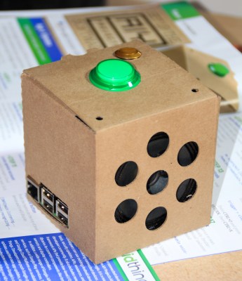
In this writeup, I layout the DIY version of the AIY kit for everyone else who wants to talk to a cardboard box. I take a closer look at the free kit, take it apart, put it together and replace it with DIY magic. To make things more convenient, I also designed an enclosure that you can 3D print to complete the kit. Lets get started.
The Teardown
A shout out to my friend [Shabaz] in the UK for sending me a copy of the MagPi. The “Google AIY Projects Voice Kit”(henceforth known as the kit) contains two PCBs and a bunch of other stuff. The Voice HAT which looks like a Sound-Card-On-A-Diet has very limited number of components. I will detail each section and draw the KiCAD schematic for the same one by one
Servos


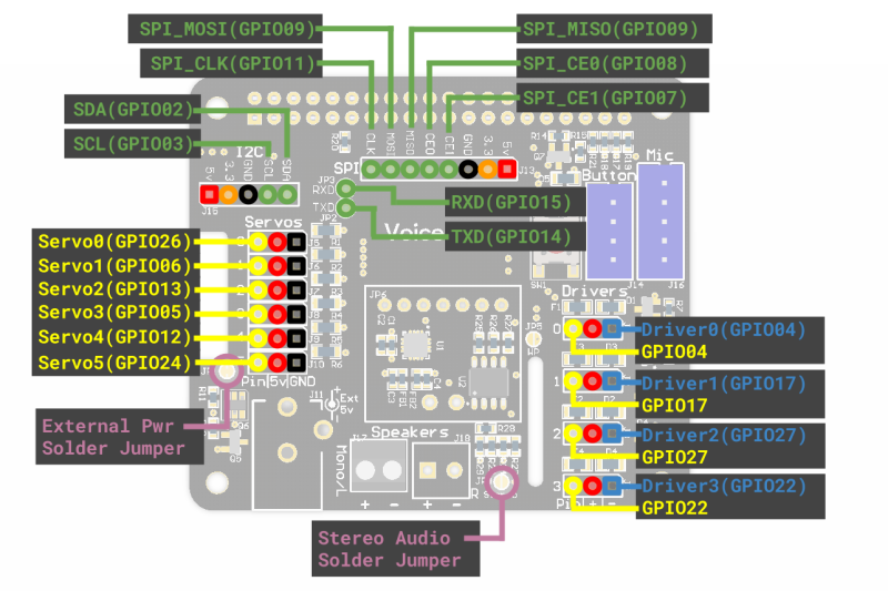
Starting from the left side, there are 6 sets of 3-pin headers that are labelled ‘Servos’. The intended servo control is made possible using the Raspberry Pi 3’s on-board PWM module. Each set has a GPIO pin, 5V and GND connection. The GPIO pin does not connect directly to the Raspberry Pi 3’s header but rather through 220Ohm current limiting resistors (labelled R1-R6).
Power Supply


Just south of these are devices labeled Q5 and Q6 which I am assuming are part of a power supply selection circuit. Correct me if I am wrong but here is my estimate. The working is simple where Q5 only turns ON when the input voltage is greater than the 5V from the USB port. A simple comparator should do so I am using the LM393 for reference.
EDIT: [Raivsr] pointed out that this could be the equivalent of the Raspberry Pi ‘Ideal Diode’.
Communication Interfaces
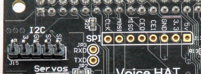 North of the ‘Servo’ headers is J15 labelled I2C that directly connect to the Raspberry Pi 3 header. That means these should not be connected to anything with 5V pull-ups. They are not being used on the board but we will discuss more on this later. Right next to it is the SPI and 2-pin UART headers. Again these connect directly to the main header and serve only as a breakout.
The DAC and EEPROM


A little lower and we arrive at the boxed circuit with a 16-Pin QFN marked ‘AKK BDQ’. This is the Maxim MAX98357A(PDF) which is an I2S DAC with a class D amplifier. It drives the speaker directly however since there is only one output, it can only be mono or combined stereo. It’s still pretty rocking for the budget.
The interesting thing is the presence of JP6 which seems to have all the I2S connections from the Maxim MAX98357A and a few other select lines. Combined with the two vias that connect to the second speaker output, you could possibly fit another Maxim MAX98357A breakout board on top to get stereo sound. I am going to do the schematic and make it downloadable and if you want to give it a shot let me know the results. Consider it optional homework.
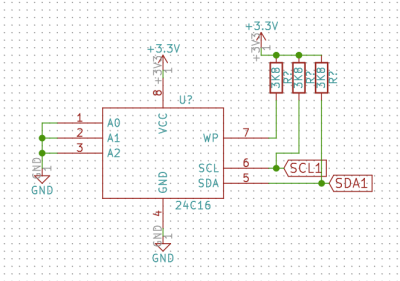 Next to the DAC is an 8-pin SSOP which is a 24C32 (PDF) I2C EEPROM. It’s not connected to the I2C header I talked about earlier but rather to pins 27 and 28 of the Raspberry Pi 3 header. According to the Raspberry Pi Foundation’s blog.
“The EEPROM holds the board manufacturer information, GPIO setup and a thing called a ‘device tree‘ fragment – basically a description of the attached hardware that allows Linux to automatically load the required drivers.”
So its got some extra sauce that makes things tick and I could use a BusPirate to Dump the data but I am not sure if Google considers it Intellectual Property so I won’t. I have an alternative for it as well so read on.
Drivers


Moving towards the right, we find 4 headers marked ‘Drivers’. These are MOSFET circuits for controlling loads such as relays. [Shabaz] did a great job tracing out the components on this one and the 3 pins are GPIO, 5V and Driver.
The MOSFETs can drive loads of up to 500mA each thanks to a polyswitch however the GPIOs are available for use directly as well. Loads to be driven should be connected between the pins marked ‘+’ and ‘-‘. The header pin on the left is a direct access to GPIOs header pins from the Raspberry Pi 3 and the schematic reflects the same.
Use these to connect LEDs or similar devices to indicate the operation of the relays or loads.
Microphone and Button Connectors
More interesting stuff is happening on the right side’s upper right with a push button and two JST connectors. The 4 pin connector is meant for the push button that sits on top of the assembled enclosure. The small PCB mounted push button is wired in parallel with the external switch and can be used in its place while setting up and testing. The 5 pin JST is for the microphone connector and has all the I2S pins.
The Microphones


 Lastly, the microphone board is marked 432 QDF21G, and has Knowles SPH0645LM4H MEMs digital microphones that talk I2S directly.
That’s It!
That about wraps up the teardown and all the information required to make your own AIY Kit. The KiCAD schematic files are available for download from GitHub however I leave you with the fun part which is the layout and routing.
Here is some food for thought. Some parts can be omitted and the size of the hat can be shrunk down to the Pi Zero pHat.
For simplicity reasons, I am using the preconfigured OS image from the Google AIY page. It is a tad short of 900MB and can be downloaded directly from Goolge (huge file).
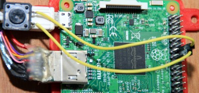
Add A Shutdown Button
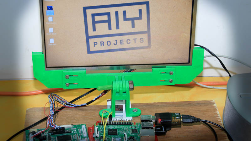
 You probably noticed the small golden button next to the big green button in the image above and that is the first part of the exercise. It is a shutdown button and is added because I don’t want to SSH to the box every time I want to turn it off safely.
Get the button you want to use and add two wires with female headers. This bit works even without the Voice Hat so feel free to try it out. Next if you have a voice hat, add male headers to the I2C part. You may choose any other pins and it will still work. Connect the button to the SDA or GPIO 2 and boot the Pi 3 up.
Open up your favourite text editor and copy-paste the following code into it.
#!/bin/python
# Simple script for shutting down the raspberry Pi at the press of a button.
# by Inderpreet Singh

import RPi.GPIO as GPIO
import time
import os

# Use the Broadcom SOC Pin numbers
# Setup the Pin with Internal pullups enabled and PIN in reading mode.
GPIO.setmode(GPIO.BCM)
GPIO.setup(02, GPIO.IN, pull_up_down = GPIO.PUD_UP)

# Our function on what to do when the button is pressed
def Shutdown(channel):
    os.system("sudo shutdown -h now")

# Add our function to execute when the button pressed event happens
GPIO.add_event_detect(02, GPIO.FALLING, callback = Shutdown, bouncetime = 2000)

# Now wait!
while 1:
    time.sleep(1)
Save the files in your /home/pi folder as shutdown.py
In a terminal type the following commands
chmod +x shutdown.py python shutdown.py &
This should make the script run in the background. If you press the button, the Pi should shutdown immediately. You may choose to add a delay by uncommenting the sleep call in the example code. Alternatively, you may also change the GPIO by replacing the appropriate number in the python script.
Cool! Now we can shutdown by pressing a button.
Add a USB Sound Card
The obvious alternative to the Google AIY Voice Hat is to use any USB Sound Cards that are available from a number of sources. The simplest way is to just plug one in and configure the software to use that instead of the Hat but when there two drivers installed, the python scripts need to be reconfigured to make everything seamless.
Once you plug in the soundcard, the first thing to do is check if it was recognized or not. In the terminal window, type in:
aplay - l
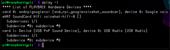 ‘aplay’ is used by the scripts to speak out the replies so you should be able to see two sound devices. Note that the onboard sound has been disabled from within the config.txt (see device tree reference) and can be enabled if you plan to use a USB microphone instead of the sound card. The windows output should look like the image below.
I would like to set the USB sound card as the default audio, and for that we need to modify the /etc/asound.conf .
sudo nano /etc/asound.conf
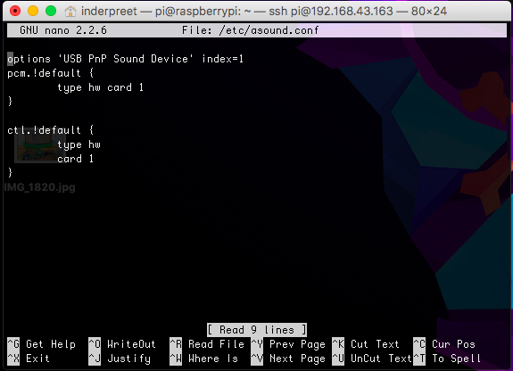
Delete the existing content and replace it with text as shown below. Though this sets the default input and output device to the USB device, there is one more step to make things work. (To exit nano, use Ctrl+x, y, return)
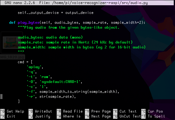
Next we edit to audio.py file that handles all the audio playing and recording functionality. For that, open up the file in your favourite text editor; mine is nano:
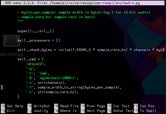
sudo nano /home/pi/voice-recognizer-raspi/src/audio.py
Scroll down to the part that says ‘arecord’ which is in the __init__ function. Apparently there is a dedicated process that keeps the recorder running as I will show in the video. For now, we want to edit the arguments so that it uses the USB Card to capture audio instead of the original Voice Hat. A simple modification to use ‘-D’, ‘sysdefault:CARD=1’ should suffice as shown in the image below.
A similar change is require for the aplay function a little further in the code.
 With that, the hack is complete! Double click the ‘test_audio.py’ to check if audio works. We are missing just one part of the puzzle though — the ‘listen’ button! So simply wire a push button between GPIO23 and the adjacent ground pin and then run ‘src/main.py’ to start playing with a DIY Google AIY.
A Demo
A small video demo of the proposed hack with a USB sound card, external speaker and a cheap microphone.
An Enclosure
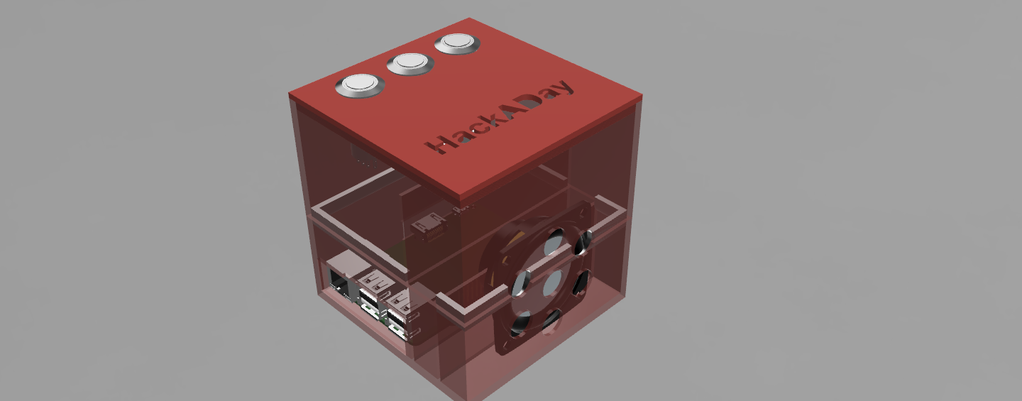
The 3D printed enclosure is designed in Fusion360 and the STL files are part of the GitHub repository. You can use the same enclosure for a number of projects since there are standoffs for the Raspberry Pi and the ports are brought out for convenience. There is a lot of space inside to add hats and additional circuits.
I made the enclosure split from the middle so that it becomes easy to access the GPIOs. The whole thing will press fit including the top cap which has holes for three buttons. I though it would make sense to have smaller buttons since the result is expected to be tougher than cardboard. There is ample space for the speaker should you choose to include one that is slightly different.
I have not had a chance to print one out and will update this page once there is any progress in the topic. Here is the render of the design.
Summary
Google has already had their APIs open to the public, but the preconfigured Raspbian image will help a lot of people to get started. I have tried to layout the basics of the sound card as well as give out the plans for an equivalent card if you want to make one. For others the option to use an external sound card is explained and demonstrated and I hope it inspires people to really get into such projects. The world needs more AIY and here is your chance to get started, so what are you waiting for? Get hacking.


Pff, Raspberry Pi is easy.
I’ve built an Amazon Alexa client (basically an Echo Dot) using just a ESP32, a Knowles SPH0645LM4H mic and a MAX98357A I2S amp. Coded the firmware from scratch in C, as is right and proper.
submit to HAD or it didnt happen
challenge accepted – still needs an enclosure, any (preferably non-boring) ideas?
A nice wooden box from a second-hand shop.
if you have access to a 3d printer, just make a black puck with the HAD jolly wrencher on the top
The other ideas are pretty standard, good but standard. Why not an empty soda can? See if you can get all the electronics fitted inside nicely with little to no visible changes to the outside of the can.
Might make for some interesting RF issues concerning wifi. I’d try to see if I could use the can as a ground plane for a patch antenna maybe?
Just a thought.
Tardis! :-)
There’s a 3D stl somewhere or get the Tardis USB hub and drop it in there. :-)
Inside a turret from Portal.
Finally a good idea. ThinkGeek made them, but they stopped making them. The cheap replicas on ebay look … cheap.
case: A Jetsons lunchbox.
A useless machine with a five-second delay on the ‘open mic’ button. :grin:
Excellent lateral thinking there.
How about a Furby?
And how do you record the audio? Can the ESP32 sample faster than the ESP8266?
Presumably the Knowles mic has I2S output like the one in the article. So no sampling really needed.
I disagree with the last sentiment conveyed in the article. The world needs fewer proprietary, spying-based speech recognition services. Still, cool analysis.
Nothing stopping people from creating a home version. It just will not benefit as much from all the data the cloud version would have.
Agreed, I was disappointed it uses Google closed source stuff. There are open source alternatives although they are quite tricky to use. Getting to use these ones that is the real challenge.
“The world needs more AIY and here is your chance to get started, so what are you waiting for? Get hacking.”
People want a Jarvis (Iron Man) for their home. If you can get it for your personal suit of armor, so much the better?
That extra eprom provides the hat ID information.
Part of the spec requires this so the raspi can recognise what hat/add on board youve plugged in.
Its fully documented. No need to break in to it.
https://github.com/raspberrypi/hats
“Unfortunately the world has more makers and hackers and the number of copies of the magazine are limited.”
Wrong. there are more selfish turds who are willing to buy up all the copys a shop has and sell them at inflated prices and not use them.
Just look on ebay and see all the selfish scum selling copy’s.
Wow. That never even occurred to me, that people would be doing that. Scum.
Buy low, sell high. Hmmm, now where have I heard that before?
Yup, saw on FleaBay one mag with the kit for $60 (didn’t look at shipping). Local B&N only had March’s issue (???). Decided to build my own (Adafruit parts).
“The interesting thing is the presence of JP6 which seems to have all the I2S connections from the Maxim MAX98357A and a few other select lines. Combined with the two vias that connect to the second speaker output, you could possibly fit another Maxim MAX98357A breakout board on top to get stereo sound. I am going to do the schematic and make it downloadable and if you want to give it a shot let me know the results. Consider it optional homework.”
Thank’s I was wondering about this set of connection points.
It should be like the dual mics, one select to ground, one to Vcc. Don’t know if the software will take advantage of it. I think other software will though.
A-I-why?
Have you considered adding a safe shutdown command instead of a dedicated button. This and several additional commands are documented here http://ktinkerer.co.uk/list-mods-raspberry-pi-aiy-project/
@Inderpreet, excellent work. Just so some of the folks know. You can get a LED lit arcade button, a proto hat with a 24C32 EEPROM, the I2S Amp (Maxim MAX98357A) and I2S Mic (Knowles SPH0645LM4H MEMs). While not the same as the AIY board, I expect it should still work with the AIY code. I have all the parts and I’ve built part of the AIY on the HAT and hope to finish in a few weeks (I have a Google Home so I can play).
And yes I based the parts list on the previous article you did on the tear down of the AIY. Very much appreciated.
Dang ….
… you can get the parts from Adafruit
I assume the EEPROM isn’t necessary. As an alternative, use a pi zero and the smaller proto hat and shrink it down to the size of the speaker.
Hmmm…Interesting work. But why go through the effort just to let Google spy on you and everything/everyone around you?
I have the impression you never see projects with hardware to protect you from google or amazon, only more enablers.
Am I the only idiot who found the instructions in the magazine didn’t match what was on the website?
Is the GPIO driver bank MosFET ‘ground’ pin really ground or is it just switched to ground. Did you ring it out on a meter because I tried to
Hi,
I do not have kit and try to follow your directions. I use RPI 3. I have problem with the section about sound card. The file /etc/asound.conf does not exist. In addition, the directory /home/pi/voice-recognizer-raspi/ does not exist, so obviously /home/pi/voice-recognizer-raspi/src/audio.py file does not exist.
I have problem with connecting audio devices. What should I do?
Thank you.
Hi, anyone interested in this may find this link useful: http://www.securipi.co.uk/voice-recognition-and-command-with-a-raspberry-pi-and-google-cloud-speech-api/
Instead of adding a button to shut the pi down gracefully you can now say “raspberry power off”. This feature was added some time ago.
https://github.com/google/aiyprojects-raspbian/blob/master/src/action.py#L287
The enclosure is missing a hole for the phono plug.
And also for the microSD card.
I have the Google assistant working without the voice hat (just a USB mic and ear buds in the jack, and a button) and
1) I can’t get LED on the button to work as I don’t know which GPIO is mapped for that. Can anyone help with which GPIO and coding to specify the GPIO of my choice?
2) Also, would like to output the sound to GPIO instead of the jack (and I’ll run it through a little amplifier board I have and connect to a simple speaker). Is there a simple way to redirect the sound? I read somewhere it was routed to GPIO 45 and 46 or something but that isn’t accessible with the pins. Apparently can be rerouted to GPIO 18 and others using an ALT modifier.(??) Above my level to figure this out. Anyone have a simple solution?
Many thanks!
About the power supply section :
How do you power the LM393 (pin 8) : from +5V from USB ? (pin 2,4 from PI’s header ?)
What if the Pi is only powered from the board barrel connector ?
Could il be better to power the LM393 from barrel connector ?
What’s the button and led connector pinout ?
If anyone wants to build a kit with me get in touch (I have responses licensed to me from some of the world’s top sci-fi stars).
I’m looking for a coder / designer to make a unit with prerecorded responses for home automation functions.
There is a chance that your pinout for the DAC + AMP is off – the output is most likely running an attenuation circuit with where you have put (C?) for capacitor.
I am curious what the gain settings are on that max DAC/AMP + those resistor values so I can see about running it into another system.
or could be filter caps if they are marked in pF.. oops!
You just triggered my AIY while I was watching the video :)
“A simple comparator should do so I am using the LM393 for reference.”
It’s obviously not, since a LM393 is a dual comparator in an 8-pin package.
The SOT26 device is labeled K4S, which looks like a DMMT5401.
It’s not the same as the BCM857BS PNP pair used on the Raspberry Pi, but the architecture is practically identical.
The SOT23 device, labeled 23X, is a DMG2305UX the same as the Raspberry Pi.
So, Google AIY has been updated, and the /audio.py no longer has the “arecord” and “aplay” settings. It appears that these settings are now in home/pi/voice-recognizer-raspi/src/aiy/_drivers/_player.py AND home/pi/voice-recognizer-raspi/src/aiy/_drivers/_recorder.py
tried opening the schematic in KiCad but it complains that some libraries are missing:
The following libraries were not found:
libraries/POLYFUSE
voicebox
Can you please upload these libraries as well?
tried opening the schematic in KiCad but it complains that some libraries are missing:
The following libraries were not found:
libraries/POLYFUSE
voicebox
Can you please upload these libraries as well?
Hi,
Thank you for your detail DIY manual.
In other site, I found a post which explained how to connect bluetooth headset to raspberry pi. So, I wonder if it is possible to make my own Google assistant using raspberry pi and bluetooth headset.
According to the steps I finally connected the bluetooth headset. But I cannot know how to configure the mic and speaker for Google assistant.
If you have any idea, please help me.