“Measure twice, cut once” is great advice in every aspect of fabrication, but perhaps nowhere is it more important than when building a CNC machine. When precision is the name of the game, you need measuring tools that will give you repeatable results and preferably won’t cost a fortune. That’s the idea behind this Arduino-based measuring jig for fabricating parts for a CNC build.
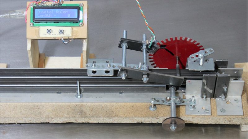
When it comes to building on the cheap, nobody holds a candle to [HomoFaciens]. We’ve seen his garbage can CNC build and encoders from e-waste and tin cans, all of which gave surprisingly good results despite incorporating such compliant materials as particle board and scraps of plumber’s strapping. Looking to build a more robust machine, he finds himself in need of parts of consistent and accurate lengths, so he built this jig. A sled of particle board and a fence of angle aluminum position the square tube stock, and a roller with a paper encoder wheel bears on the tube under spring pressure. By counting pulses from the optical sensors, he’s able to precisely position the tube in the jig for cutting and drilling operations. See it in action in the video after the break.
If you’ve been following [HomoFaciens], you’ll no doubt see where he’s been going — build a low-end tool, use that to build a better one, and so on. We’re excited to see him moving into more robust materials, but we’ll miss the cardboard and paperclip builds.


Clever and awesome as usual. This guy knows the basics and knows how to make everything from cheap materials.
Metalworking precision and a solid base workshop do the rest
Well done
But does it really need to be this complicated, when a simple backstop and a ruler would suffice?
Often the absolute size of a part is irrelevant, and the relative size to its mating piece is paramount, which is where the backstop does a perfect job while the counter wheel has large uncertainties and your structure becomes wonky.
I have build the first iteration of my CNC v3.2 your way and for sure there is no need for an electronic jig, but we are hackers that don’t stop searching for new ways of doing common things, aren’t we?
I expect to get the drill holes with a higher precision and quicker. I will report if it works better than the old way…
““Measure twice, cut once” is great advice in every aspect of fabrication, but perhaps nowhere is it more important than when building a CNC machine.”
The “how to measure” is important as well.
This is in stark contrast to my dad and I drywalling my dad’s basement. We’d measure once, both remark about how the mark didn’t look right, cut anyway, tack the drywall up, keep hacking chunks off until it actually fit, patch all the damage, then repeat for the next panel…
Impressive. I’ve been ruminating about a simple “computer controlled” stop block for my mitre saw and this looks like an interesting approach to a similar problem.
He has a lot of good videos. I like the servo motor teardown and recreation one.
https://www.youtube.com/watch?v=v2jpnyKPH64
Great work as usual. I enjoy his videos for detail and clarity, and the voice is just awesome.
The design doesn’t look too “highly” accurate because of the relatively small number of quads. I probably would have used a PC mouse that still supports PS2 mode as the protocol is quite simple and the resolution is much higher. It could probably be used direct to the material instead of having a driven wheel.
There are already some existing libraries –
https://playground.arduino.cc/ComponentLib/Ps2mouse
The number of quads is high enough to get a resolution of around 0.2mm in theory and around 0.5mm in practice, which is good enough for hand cut parts (at least for my machines).
The mechanical computer mice are indeed an option, but you must make sure the ball rolls without slippage on the surface. Optical mice are no good idea as I have evaluated in another video:
https://www.youtube.com/watch?v=CIRKRzw54Zs
Well that is very interesting.
I haven’t tested a mouse to that degree. It looks like the mouse firmware includes some acceleration.
I will see if I can connect a micro directly to the optical sensor.
Thanks for the great video.
Great video, just one correction: cheap super crap optical mice are not good.
rerun your test using something with Avago (Pixart) 3310, 3360, 3366, 3989 etc, basically hiend mouse sensors aimed at gamers that will cry bloody murder when mouse has acceleration or is non linear. Now I say hiend, but in reality you can get mouse with one of those sensors for $10 or even shipping cost, just find one with broken switches.
old thread https://geekhack.org/index.php?topic=56240.0
I see the Logitech G 303 listed, but not the 302.
It’s a G303. Did I say G302?
The Logitech G203 isn’t a cheap one, is it? Even the best ones do some sort of firmware corrections of the raw data. You won’t find a device that gives you absolute positioning capabilities with error free repeatability.
The G303 is listed in your thread having no acceleration and prediction and it doesn’t work either.
Sorry, you are right about Logi 303 being decent, too bad you didnt specify model anywhere in the video nor the YT description :(
I read your website, rewatched video and did some research, got few things:
-you user Pee instead of computer with Logi driver/app combo. Sounds stupid, but their app sets the mouse up with proprietary magic.
-you used ridiculous marketing 12K dpi mode :), and more sanem, but still not great 3000 mode.
if you still have this setup try 400/800 dpi and 1000hz pooling reading mouse position on a windows (sadly)PC with logi app/driver. Again it might sound counter intuitive, but higher pooling and lower dpi makes the mouse scan faster and introduce less artificial artifacts. 3366 sensor might be advertised at 12K dpi, but it does ninja smoothing past ~2000dpi.
The reason why the mouse sensor through USB is inaccurate is because the mouse sensor reports a certain number of counts per inch, which gets scaled by a constant in the Linux operating system that is reading the mouse to translate it into pixels per inch, and this introduces rounding errors.
It’s fairly simple, at least in simpler optical mice, to interface directly with the camera chip if it’s one without a SoC microcontroller. You can poll it directly with a microcontroller to get the raw data in the actual sensor resolution out, without acceleration or other effects.
Of course the problem is that the sensor raw data may be as low as 400 counts per inch, and when moving slowly, let’s say an inch a minute, you only get a blip up every 150 milliseconds. That makes it difficult to create feedback loops because for most of the time your polling function is returning 0, 0, 0, 0, 0… and you don’t know what the speed is until you’ve advanced at least 2/400th of an inch (0.127mm) by which time it’s usually too late.
The resolution problem may be resolvable.
I have had mouse mats that are patterned and quadrupedal the resolution. I expect they have a pattern like a Fresnel lens that introduces extra refractions.
Nice! Don’t forget to factor in the kerf width of the blade!
I made a way to accurately cut thin/ accurate pieces on a table saw:
https://youtu.be/H-2uW7gSRXg
Nice. How did you secure nuts within the movable piece? Just friction fit?
+1
I like my lock nuts. That little bit of nylon does wonders.
I just drilled a slightly smaller hole than the max width of the hex nut and tapped them in. I practiced on other scrap to get the right size.
Thanks. This might be useful for my next, simpler and better, cnc machine :)
Are you able to share the source code?
Thanks