[Josh] posed an interesting challenge. Create a boost converter that can light a blue LED using a nearly dead battery and one part. Well, we were skeptical until we saw he wasn’t counting an ATtiny processor as a part. You can see a video of the challenge, below.
The challenge has already been solved, so if you view the link, you might want to avoid the comments until you’ve had time to think about your own solution. We’ll confess, the first one we thought of was probably not workable for reasons [Josh] explains. The final answer neatly fits the criteria of a hack.
While the solution is tricky (and, no, we won’t give it away), we can say that it isn’t a “cheat.” There’s no other power source hidden somewhere or anything like that. The end result is legitimate and satisfying and takes advantage of a documented chip peculiarity.
In the end, the real read is in the comments, but give yourself some time to think about it, first. If you want an example with more than one extra part, we’ve seen plenty of those. If you want a refresher on how it all works, you might enjoy this post.


Norwegian Blue? https://www.youtube.com/watch?v=4vuW6tQ0218
I’m no mathematician but I count two parts.
I suspect all you would need to do is place the inductor in series with the battery connected to the tiny’s power rail. By oscillating the power modes of the tiny, you can create a low/high characteristic impedance swing that would charge the inductor to a point you could operate the tiny at least 2x the battery voltage (no tank cap) for up to half of the total real time. The LED is just connected between an output and ground. Atmel’s have enough series resistance on gpios they rarely need limiting resistors at low voltages.
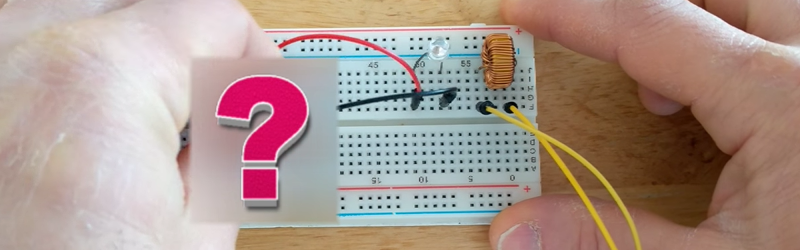
Aside from the LED, battery, holder and wires, this circuit has two parts – the chip and the inductor.
I think you have to connect the inductor between the Battery + and an output uf the ATTiny and connect the LED to it’s VCC pin (and GND). Then the output stage could work as a synchronous rectifier – step-up
No micro needed…
Battery, Inductor, Thermistor, LED.
Thermistor in parallel with the LED.
Thermistor is low resistance when cool, storing energy in the inductor.
When the thermistor gets hot, the resistance goes high, and energy stored in the inductor lights the LED.
You might need to experiment with different thermistors to find one that can cycle fast enough that you don’t see the LED flicker. ;)
Why not just make a “joule thief” while you’re at it? :p (Way more efficient than what you’re proposing)
Also, are you sure that a nearly dead battery can heat up a thermistor enough to change its resistance? :p If that’s the case you need a thermistor with a brutal dR/dT.
I stopped reading when I noticed the author does not know how to count. 1 inductor + 1 avr processor = 2, not 1.
Same, not playing this game.
I think what’s being implied is passive parts vs active.
Then a MUCH BETTER circuit can be done with one transistor and a transformer (Joule thief). The tricks and discussion are OK, but the title of this post and the original article are CRAP.
Which even works down to 0.5 V and is cheaper and more robust.
Why has the name “Joule Thief” become so popular?
Circuits like these were already around when I was a kid, and LED’s were still rare and expensive (as were coin cells), so it was pretty common to power a (red) LED with only one cell, using a one transistor + transformer circuit.
Also nearly all xenon flashlights in cameras worked that way, only with bigger transformers and capacitors.
Ages before the Joule Thief.
Same reason we now have shields instead of daughter boards, the latter being a much less confusing name that allows anyone to know what it is without being told. Or in a nutshell, snobbery.
http://www.bigclive.com/joule.htm
“joule thief” is popular because inductive boost with a free-running oscillator is a mouthful :)
Same reason we have the semi-literate “corner case” or “edge-case” instead of “boundary condition”, which came from the language of differential equations, which are crucial for circuit theory. And we now have to read the asinine “use case” instead of “example”. People need a word to describe something and they don’t spend time with experienced practitioners who know the lexicon. It is funny that the Internet is the force behind much more rapid drift in language at the same time vocabularies are shrinking dramatically.
It is doubly puzzling because when there is a story about, say, sand casting, there are plenty of comments on the proper terms for the various tools and parts.
I struggled too. He did say “no transistor” so it isn’t active vs passive. I think the intent (and I’m guessing) was to say “You already have a MPU. How do you add a boost converter with one additional part?” Key word being “additional” — so you don’t count the LED because it is the load. Ditto for the battery and wires which you already have.
Anyway, I still thought it was interesting regardless of how the question was phrased.
Worst use of an MPU ever. Sorry.
And instead of using 1 transistor he is using SEVERAL THOUSAND (inside the MPU). Again, I like some of the discussion but misleading titles matter.
Of course, the requirement of “no transistor” would instantly rule out using a microprocessor, which is made of…. transistors!!!
Again I think his point was…you already have the mpu. The single part is the delta. I personally applaud people who take the time to write up things even when they aren’t how I would do things or I don’t agree with the way they characterize it. At least they are putting things out in a positive way and simulating discussion.
I guess you could always ask him to refund your money. Oh wait….
How about an inductor switched at a couple kHz by a relay hooked up to short its own coil? (2 parts)
Or better still, use the coil of the relay as the inductor, basically just use the LED as the flyback diode. 1 part.
How many seconds do you estimate the relay will survive? :\
A relay wired to oscillate itself is basically identical to an electronic vibrator – a very common part, back in the day, for DC-DC conversion in devices such as vacuum tube radios.
https://hackaday.com/2016/07/04/retrotechtacular-dc-to-dc-conversion-by-vibrator/
I’ve done it before. The relay died in 5 or 10 minutes.
I’ve done it accidentally, lasted seconds and melted. Obviously wasn’t rate for that duty.
That’s exactly how my dad tried to explain me how switching converters works when I was a kid.
I did not understand much at first (being ~10yo at the time did not help), but it made lots of sense a few years later.
I have the oddest feeling that this could have been done with a 555. Maybe set it to trigger a voltage drop when the coil finishes building its field. It might just be self-regulating if the coil is at the right impedance. I don’t know for sure, but just throwing that out there.
I don’t think so. The 555 is meant for much higher voltages. The idea is that this works down to 1.8V (according to spec) and a bit further off-spec.
http://www.ti.com/lit/ds/symlink/lmc555-md8.pdf
I thank you. I was hoping I wasn’t completely crazy.
Joule thief is better, but LM3909 will double the voltage and flash the led and was invented for such purposes in the 70’s
I loved the LM3909 – I used it in the first circuit I built containing an IC. Years later I found it and gave it to a friend who wanted to use it as warning LED in a dummy car alarm.
It’s hard to get now, but you can abuse ICL7660 to make something similar.
You can get loads of them in DIP on Aliexpress. I got 100 a couple months ago for something like $18. There is an improved part in manufacture now. Maxim? TI due to all the mergers? I use them for dual supply op-amps.
I think what is going on here is that the coil is connected to two GPIOs, with the pins alternating, one with a high and one with a low, then reverse it, possibly also using the tri state high impedance. This way you charge and discharge the coil. The flyback of the coil is then rectified by the pins protection diodes since the coil output is higher than the battery input. It then powers the mcu and ultimately the led, which is connected to another GPIO and ground.
It doesn’t need the pin protection diodes for that; the LED itself can do that by being wired directly across the inductor. In fact, the protection diodes are somewhat problematic because they will clamp the pins to the power pins. But it’s not a problem in this specific case because adding two diode drops to the 2.7V power input allows the difference between two pins to be up to 2.7 + 0.6 + 0.6 = 3.9 V.
It needs to control the led though, so if the mcu is used as a pwm to control the led brightness, the mcu needs to be powered, unless there’s an open collector in the mcu.
imqqmi: I was responding to your post, which I believe assumed you could control the GPIO pins with the ATtiny. I was only pointing out that no external rectifiers are necessary because the LED itself can perform that function.
In a way this discussion of what to do vs the traditional way reminds me of code obfuscation contests. It works, but good luck understanding it on the first try.
I like this 2 part (“1 part” if we go by OP standards) mechanical boost converter better https://www.youtube.com/watch?v=iHmTc0PwiyY
I wonder it could be made a true 1-part by nixing the transformer and making the magnet coil bigger then put the LED across it instead so it would act as both a flyback and mechanical switch
The OP this article refers to says:
“Goal:
Build a software controlled boost converter using only one part (an inductor). It must be able to generate at least 3.7 volts to drive a blue LED from a 2.7 volt source.”
It then goes on to list four parts in the next paragraph, assuming the general convention that interconnecting conductors don’t count as “parts”. I’m done with it at that point.
I would have answered a tunnel diode. Can light a LED with less than 200mV and requires no software.
http://hackaday.com/2016/03/30/a-ridiculous-way-to-light-an-led-candle-power/
It has been done before. How many of you have heard of the well documented boost feature of Cypress PSoC 3 and PSoC 5?
That battery… It’s not dead, it’s MOSTLY dead.
http://uploads.neatorama.com/images/posts/96/93/93096/1477157576-0.jpg
i did a from scratch buck converter, but it required quite a bit more than one part. i used a 555 to generate the switching frequency, a power transistor, an opamp in comparator mode, and a and gate made with a couple mosfets. id and the output of the 555 with the result of the comparator to switch on and off the transistor. the comparator compares the output voltage with a zener diode reference voltage and interrupts the clock if the voltage gets too high. i tested the thing at 500ma and it held steady at 5v. i actually did try to reconfigure it as a boost converter, and it worked but only boosted it a couple volts above input, and i couldn’t draw much power either.
one part? thats cheating!
No need for ATtiny, transistors, etc. Just the inductor.
And all you have to do is connect the LED in parallel with the inductor, then (briefly) the inductor in parallel with the battery. When you disconnect the battery, the inductor current will want to go somewhere, therefore through the LED. The LED might burn due to excess current but, hey, stated is solved (they didn’t say how long the LED needs to be “on”, just that it needs to light up).
In essence this is how a boost converter works. For better current control in your LED you need precise timing. Does a robot pushing/pulling jumper wires count? It is not a “part” in the circuit :-)
https://www.romanblack.com/smps/pic-smps.htm
As said, this is a two parts circuit. But as a bad reader,I suggest you to take a look at the rest of is work. Some of it were already mentioned in at least one article.
Sorry, this is a buck converter, anyway, this is the principle…
well, if you really wanted a single part, there are integrated DC DC converters http://www.mouser.com/ds/2/281/LXDC2HL_Series_datasheet_E-837146.pdf which count as 1 part to me.
Do I have to count tbe battery? Ok. Cuz wire on a nail is not a part, ;>). Make an autotransformer and touch 2 wires for the orimary and tap the secodary or all of it. Who needs an LED?