Forgive the click bait headline, but the latest work from [Marco Bartolucci] and [José A. del Peral-Rosado] is really great. They’re using multiple HackRFs, synchronized together, with hybrid positioning algorithms to derive more precise localization accuracy. (PDF)
 Like all SDRs, the HackRF can be used to solve positioning problems using WIFi, Bluetooth, 3G, 4G, and GNSS. Multiple receivers can also be used, but this requires synchronization for time-based or frequency-based ranging. [Bartolucci] and [Peral-Rosado] present a novel solution for synchronizing these HackRFs using a few convenient ports available on the board, a bit of CPLD hacking, and a GNSS receiver with a 1 pps output.
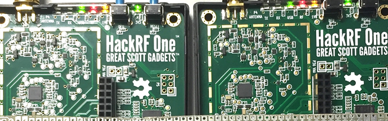
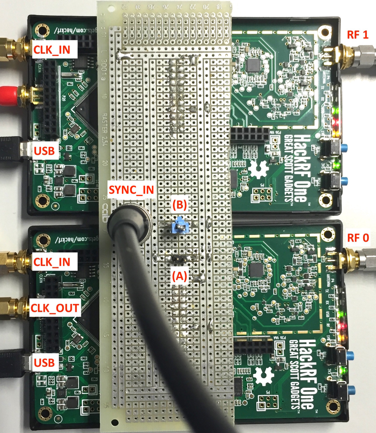
This is technically two hacks in one, the first being a sort of master and slave setup between two HackRFs. Using the Xilinx XC2C64A CPLD on board the HackRF, [Bartolucci] and [Peral-Rosado] effectively chain two devices together. The synchronization error is below one sampling period, and more than two HackRFs can be chained together with the SYNC_IN port of each connected together in parallel. Read more about it in their pull request to the HackRF codebase.
This simplest technique will not work if the HackRF receivers must be separated, which brings us to the second hack. [Bartolucci] and [Peral-Rosado] present another option in that case: using the 1 pps output of a GNNS receiver for the synchronization pulse. As long as both HackRFs can see the sky, they can act as one. Very cool!


This was a little confusing at first. I’m thinking “I’ve got my GPS disciplined rubidium frequency standard connected to my HackRFs. I’ve got SYNC_CMD connected to SYNC_IN”… So what’s the point of the 1PPS?
Nice. Shame HackRFs cost so much.
They are delightfully cheap when compared to anything with similar capability.
Then again, with a LimeSDR you’d have two synchronized inputs without any hackery like that. Synchronizing multiple LimeSDR’s currently seems hard, a friend tried it with bad results, the phase constantly drifted.
But I do wish we’d get the RTL-SDR or transmit capable SDR’s. That would be a fun can of worms.
I suspect it’d come out of software modified 3g/4g dongles. The baseband stuff in those is seriously capable, but very closed.
So, they use a GNSS receiver to get the time signal for position measuring?
I wonder if this could help with those trying to make more affordable gunshot locators.
In case anyone else is wondering what the heck is going on here, I will summarize:
These researchers want to synchronize 2 SDR’s together (for applications which require digitizing data from multiple antennas and/or on multiple frequencies outside the SDR’s bandwidth). Their solution was to modify the firmware on the hackRF so that 2 radios so that multiple radios can be triggered from an external source, instead of being triggered over USB. They did this by ANDing the USB trigger with one of the user IO pins, so that capture does not start until it has been requested over USB and there has been a rising edge on the sync line. This sync signal is chosen to be at 1Hz (configured to acquire a 1s long acquisition…) and can come from a hackRF, or an external trigger source. The latter is useful in applications where it is not practical to run a sync wire between the radios, in which case the 1-pulse-per-second output from a GPS can be used as a timing reference between units in distant locations (you would of course also need to provide accurate time bases for both units, and a way to transfer the data to a central computer…).
They then chose a very roundabout method to verify their results, by recording GPS and LTE data (both of which provide accurate timing information) using their synchronized radios, and showing that the recovered timing information is accurate to within a nanoseconds, which less than the sample time of the analog/digital converter (20MHz).
Finally they submitted a request to the hackRF team to add their additional sync logic into the CPLD on the hackRF so that others can try out their techniques.
A nice example of an application where the open hardware nature of the hackRF allowed it to be repurposed for an use case the original did not design for.
I have the impression that GPS time signals are not very accurate due to atmospheric disturbances. A better approach might be to use the time signal from cellphone towers. Better yet, to use a signal from the various longwave time standard transmitters. A good quality PLL could then shift up the signal to be near the band you’re interested in, so you could recover it from your data.
That at least is how I plan on doing it once I get through my backlog of interesting projects…
The error in GPS time is about one nanosecond per 0.3 meters of position error.
Good GPSDO designs can give you sub-ns accuracy and stability. They usually use a high end TCXO or atomic standard for the short-term while syncing to the GPS over sub-mHz time scales.
Multi-band GPS timing receivers are also able to correct for ionospheric disturbances as the ionospheric delays are frequency correlated.
The majority of towers grab timing from GPS. In fact, in some implamentations, every node keeps time independently.
> Like all SDRs, the HackRF can be used to solve positioning problems using WIFi, Bluetooth, 3G, 4G, and GNSS.
wat
Show me how to do exactly that on a 0-30 MHz KiwiSDR, or a SoftRock Ensemble setup for 160 meters / 1.8 MHz. Oh wait, you can’t, because that sentence was complete bullshit. They have nor the range nor the bandwidth do solve problems using any of those standards.
I think that was just their slightly sloppy way of trying to indicate that there’s nothing particularly HackRF-specific about this hack.
I saw this and had multi resolution freq reading. Awesome project and kudos to Marco and Jose.
We had a similar article that spoke about VHF? UHF? transponder switching. And thought about if multiplexing a bunch of those cheap USB SDR dongles and if one could rewire a few for TX for half duplex between switching.
I’m attempting to sync the HackRF One to 1PPS signals following the idea seen in the Bartolucci paper. However, I am not able to reproduce the synchronization accuracy that he reports.
I rebuilt the firmware from the master thread in github and installed it.
I rebuilt the command line tools for the Raspberry Pi platform being used.
I have my 1PPS signal going to P28 pin 16. The schematic labels it B1AUX13. It goes into the FPGA (XC2C64A) pin 55. The FPGA pin is labeled BANK1F4M13.
I’m expecting it to begin capturing data on the very leading edge of the 1PPS signal or a time very close to it (e.g. tens of nS difference). Instead, I am seeing what looks like a variance of about 1 mS.
My hardware does wait for a sync signal before it starts capturing so it is, more or less, working. However, the timing for the captured data appears to move around about +/- 0.5 mS. The FPGA does output the HOST_CAPTURE signal as expected about 25 to 75 nS after HOST_SYNC (1PPS) appears on its input. However, for some reason, the MCU does not begin to capture data at consistent times.
Can anybody provide some help or suggestions on this? Can a get a firmware binary that is known to work?
Thanks,
George
I found that I have to reset the HackRF before each data capture to get time-synced data.
And this poses a different problem as the gain settings that I provide with the “hackrf_transfer” command take about 5000 samples to settle down at 15 Msamps/sec.
I don’t know exactly what is going on but I have a hypothesis. It seems as if the A/D data is going into a FIFO buffer. The first capture works perfectly. However, subsequent captures pick up samples that were left in the FIFO buffer. This causes the time sync to be lost. If I reset the HackRF, the FIFO buffer is cleared out and the next capture is time synced.
That’s just my hypothesis based on my observations. Maybe somebody can confirm or suggest a better explanation. It would be better yet if somebody could provide a solution.