If you buy a serious scope these days, it is a good bet it will have at least two channels. There is a lot of value to being able to see two signals in relation to one another at one time. Even though the dual-trace oscilloscope goes back to 1938, they were uncommon and expensive for many years. [Mr. Carlson] found a device from 1939 that would turn a single channel scope into a dual trace scope. In 1939, that was quite the engineering feat.
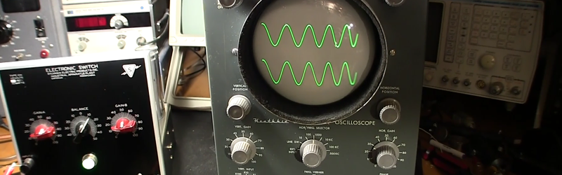
Today, a dual trace scope is very likely to be digital. But some analog scopes used CRTs with multiple beams to actually draw two traces on the same screen. Most, however, would draw either one trace followed by the other (alternate mode) or rapidly switch between channels (chopper mode). This Sylvania type 104 electronic switch looks like it takes the alternate approach, switching between signals on each sweep using vacuum tubes. You can see the device in action in the video, below.
The inputs and outputs of the device are just simple binding posts, but the unit looked to be in good shape except for the power cord. [Mr. Carlson] does a teardown and he even traced out a hand-drawn schematic. Fair warning. The video is pretty long. If you want to get right to the switch actually driving a scope, that’s at about one hour and seven minutes in.
We doubt we’ll see a tube-based Quake game anytime soon. If you want to get into restoring old tube-based gear yourself, you could do worse than read about radio restoration.


Working with antiquated technology? Humans are weird. ;)
it drives me crazy, that he didnt fix the slewed x-axis
here is the schematic, please tell us how you would go about that
http://www.heathkit.nu/O-12_schematic_2048.png
Maybe the “horizontal position” potentiometer (down left) has something to do with the horizontal position.
The horizontal sweep would ideally be a perfect linear sawtooth, but that’s visibly not the case. I’m far from an expert at tube circuit topology, but V6 appears to be the sweep oscillator. I would check the capacitors in that section for degraded characteristics.
Anybody else?
yeah, that’s a super common problem on these older scopes. The timing caps for the sweep generator are probably actually in pretty good shape, given that they’re ceramic disc. Agree with Reboots about checking the caps around V6; they’re probably paper wax and both electrically and physically leaky. I’d also check all the power supply voltages, and start checking some of the higher value resistors which tend to drift high.
V7A and V7B form a totem pole output like half of a modern day “H” bridge. These two tubes have to be driven out of phase and the phase relationship is determined by how well the two 0.1uF 200V capacitors are matched. If they don’t match well the the “X” axis will be non-linear.
Anyway that would be the first thing I would check. In any case many of the liquid electrolyte capacitors are likely to be poor condition.
The second thing I would do is swap V7A and V7B to see if the non-linearity shifts to the other side of the screen. If it does shift them you have a worn out valve or one of more high resistance (fault) bias resistors.
The Designations D3 and D4 is the horizontal drive and you can see these designations on both the horizontal drive circuit and the tube itself.
swap V7A and V7BNot possible as it’s a dual valve.
One could swap with V5 or V6 (both 12AU7) and look for changes in the sweep. Thanks for the educational comment.
this guy has some awesome videos. He’s really good at presenting information in a way that leaves no question unanswered and isn’t boring. I wish my actual professors were this good lol
Nice piece Of historic.
Reminds Me Of the Heathkit Electronic Switch I have stashed in my attic: a tube based chopper to put in front Of a Single channel scope in order to See 2 traces.
I have the same Heathkit scope- I got it when I was in high school, probably 1955 or so. I would love to get rid of it, but I cannot make myself take it to the dump. I guess that will happen when I’m gone and my family cleans out all my old junk, but at least I wont know it. Anyone have an idea for a good home for an old scope?
Post an ad online and ask a simple question that will make you sure it won’t be repurposed for some art project.
There’s a heathkit collectors group on Facebook, I’m sure someone there would like it.
I do know a good home for it. It’s called my ham shack!
My Dad has that exact Heathkit ‘scope. Back when I was in high school (late ’70s), I made a dual trace adapter for it using an analog switch IC. Interesting project, but limited in usefulness with a 2MHz ‘scope.
I see him touching the glass tubes with impunity. I have been told that doing so leaves finger oils on the glass which then causes heat to gather in that spot shortening the life of the tube. I’ve heard the same about lightbulbs.
But… is it true? It always sounded like BS to me but I’ve been careful ever since hearing that just in case.
I think that’s more for quartz glass bulbs, like headlights or projector bulbs that get really hot. Never heard that rule for normal lightbulbs or tubes.
That’s famously true for halogen bulbs. But most valves don’t get that hot.
I would wipe them clean just in case I’m incorrect though.
I’m still old school enough that for taking quick notes I find pencil and paper to be most convenient.
But.. listening to him describe re-drawing the schematic all over again multiple times to make things fit as he reverse-engineers the device…
Wouldn’t using a cad program be a whole lot easier?
In the past when doing circuit tuning, I’ve found my self printing out the schematic from Altium and then writing in all my changes on the paper. A little bit of both paper and digital.
I’ve done similar things when reverse engineering, sometimes it’s nice to have physical notes you can flip through to compare.
Personally I feel like the speed of reference on physical mediums is superior to digital ones. However, that’s simply my personal workflow, I’m sure many people have work flows that use only computers that are perfect for them. Mine just happen to be somewhere in between.
I have done computer simulations on this “valved” device. It is interesting to see how busy the capacitors really are. I can see why the old wax ones melt down. The vacuum tubes were simulated by resistors as they are not available on the simulation software. The tubes are simply current valving devices.
The problem with the X-axis is not apparent to me yet. I own the Heathkit O-11 and have modeled many of the circuits. Mine has the same issue with the “slewed” X-axis. My son is interested in the Z-axis of this scope as it may lend itself to full 3D capability.
Just think, 2 channel, full 3D capability. Would anyone ever find a use for it? LOL.
I have ordered a new cathode ray tube (CRT). So maybe that is why the trace is being compacted at the end of the sweep (slewed)?
Nope. Same exact slewed trace with a fresh 5UP1 (CRT). Next thing I would try is a fresh 12AU7 (horizontal sweep tube), however mine looks to have a pretty fresh getter. So, that may come later.
The O-11 manual does mention focus issues at the right side of the CRT, which is perfectly normal for this unit. The manual says it is due to amplifier design and compromise between sensitivity and bandwidth; whatever that means.
I came across a RCA WM-541a and haven’t a clue what it’s for? Convert Oscilloscope to Dual Trace? What is it used for?
Thank you