Once you fall deep enough into the rabbit hole of any project, specific information starts getting harder and harder to find. At some point, trusting experts becomes necessary, even if that information is hard to find, obtuse, or incomplete. [turingbirds] was having this problem with Bessel filters, namely that all of the information about them was scattered around the web and in textbooks. For anyone else who is having trouble with these particular filters, or simply wants to learn more about them, [turingbirds] has put together a guide with all of the information he has about them.
For those who don’t design audio circuits full-time, a Bessel filter is a linear, passive bandpass filter that preserves waveshapes of signals that are within the range of the filter’s pass bands, rather than distorting them in some way. [turingbirds]’s guide goes into the foundations of where the filter coefficients come from, instead of blindly using lookup tables like he had been doing.
For anyone else who uses these filters often, this design guide looks to be a helpful tool. Of course, if you’re new to the world of electronic filters there’s no reason to be afraid of them. You can even get started with everyone’s favorite: an Arduino.


Come hang out on freenode IRC and chat with the creator directly! ##hplusroadmap
What’s “hplusroadmap”?
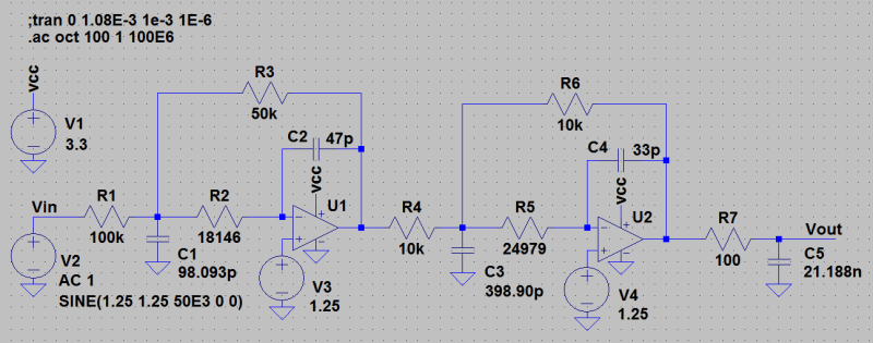
You can’t say it is “passive filter” as it use OPAMP.
+1 At least the image chosen depicts circuits that are about as active as you can get.
Bryan’s statement was
“a Bessel filter is a linear, passive bandpass filter that preserves waveshapes of signals that are within the range of the filter’s pass bands, rather than distorting them in some way”
His example is an Active Filter of the MFB Configuration, easy to implement at audio frequencies for example. But it can be done with LC Components as a Passive Filter as well. That technique would be used at RF and Microwave to achieve low group delay in broadband and UWB communications.
The statement “rather than distorting them in some way” should be ” rather causing phase distortion”.
Nice piece of work. But life is short, for the practical designer, normalized tables will do over 99% of the time.
You are absolutely right! There are good tools out there like TI’s FilterPro. The reason I made this notebook is as an educational tool, that is, to make sure I know what I’m doing, and where the numbers are coming from, before black boxing the design process. Which, in the end, is probably the right thing to do. ;)
an aside that impresses me is the quality of this GitHub page: https://gist.github.com/turingbirds/5fa6275781232c1c4e563a43c4042bf2
… okay it’s an iPython notebook, but it’s well designed and renders great on GitHub
Agreed, it is an exemplar for project documentation.
Are you a public school teacher by chance?
Nope, however I do have a tribe of my own offspring who receive a secular STEM based home education, from myself and my wife.
Just wondered. When I was teaching, “exemplar” came into the lexicon of pedagogy and it was everywhere, along with “rubric”. I had never heard of “exemplar” outside education, and never heard “rubric” used to mean a table of lesson planning goals or similar tables. A rubric is a rule, but Ed School eggheads have developed their own special meaning.
When I worked at Sekidenko/Advanced Energy (designing stuff for AMAT) there was an ex-Navy guy running projects who called the lists of things to do a “provido”. It took a while to figure what the hell he was talking about. Apparently logistic people used it the same as “provide”. Never heard it since.
Yes, so much locked up in textbooks.
OK, this seems to be another “cloud” ball-and chain thing using iPython/Jupyter:
https://en.wikipedia.org/wiki/IPython
From a first-glance this seems to be a poorly documented (nah the Github link doesn’t have any easy to find doc details, at-least without allowing a LOT of scripting which I’m not going to do).
It seems this thing DOES generate a netlist and schematic for LTSpice, but I don’t see any mention of this (again, where’s the documentation?)
Look, if you want to prototype analog active or passive filters there are tons of free (some open, some not) applications out there. TI has some (passive or active). Tonne Software’s Elsie is another. Elsie exports to LTspice native, but is not open-source and it’s filer order limited without paying. But Elsie is a completely free download, but x86/Windows only. It works in Wine last time I tried.
In the Spice simulation phase you need to fully understand filter responses and how to normalize your source vs. load characteristics to get meaningful results, especially in the frequency doman (Spice AC analysis). This is not so simple. The Devil lives in the details!
In my opinion the worth in what I’m seeing at first glance by this person’s work probably lies in examining the source code to see how to generate LTspice nelists/schematic files in Python. Not much else.
What do you mean by “cloud ball and chain”? It’s just an IPython notebook you can download. This isn’t a circuit-design tool, it’s an educational guide, and you’re free to download the notebook and screw around with the equations. And he has a SPICE simulation showing the AC response at the end…
Roll your own, https://hub.docker.com/r/jupyter/jupyterhub/
Yes it is possible to deploy JupiterHub locally on a network, but that’s only needed if there are multiple users to support (as in a classroom or course laboratory setting). If not, then the author of the subject suggest you latch on to the existing Cloud nipple. That’s what I mean by “Ball and Chain Cloud”. If one person is doing the development, skip the iPython/Jupyter stuff and (if possible) just extract the relevant part of the code for local use.
Hey, there’s no need for a cloud ball-and-chain! (Not too keen on those myself.) On Ubuntu, you can just do an apt-get install for the packages python-dev, ipython and jupyter. You can then locally run jupyter-notebook and access it through your web browser at localhost. I like notebooks a lot for quick tinkering and experimentation—less for “production” work, indeed.
Thanks for the tip on Elsie!
“…You can even get started with everyone’s favorite: an Arduino.” Perhaps. If you’re only working with milliHertz signals.
Are you seriously suggesting the use of of a slow, serial (I shouldn’t have to say that) microcontroller to do work that demands one of the faster DSPs you can get? The reason an op-amp works in this application is because it has one spec not mentioned: it has to be fast.
You need to quickly print some sort of “I was only kidding” clarification/retraction post so that the impressionable young people new to our business do NOT get the wrong idea(s) regarding this very important topic. We’ve already got enough self-taught non-thinkers running around jabbering, “I can do ANYthing with a microprocessor.” You haven’t done them any favors.
I would suggest that you have gotten a ridiculous number–one (1) would be a ridiculous number–of people, all different types, thinking, “What’s the big deal? I can do that with a Raspberry PI.” Not a smooth move on your part.
A Bessel filter reference is nice. Any chance of a Chebyshev one as well?
Bessel, Elliptical, Chebyshev, and Butterworth are just names for different specific ratios of R and C, with different well-defined properties. You can go look up Chebyshev values online and plug them straight into this sim. That would actually be super instructive. Or start with the Bessel and tweak the R/C values a bit and watch what happens to the phase response, etc.
This looks like a great filter sim. I haven’t played around with it yet, but it looks like it doesn’t hold any punches.
One minor quibble: the filter topology choice. The MFB filter looks great on paper, but ends up being significantly more demanding of the op-amp’s performance than, say, a Sallen-Key design. Probably no biggie unless you’re pushing the limits of what your op-amp can handle, but my guess is that an SK topology would behave more like the sim in the real world than an MFB. I usually use marginally workable parts (which is my own damn fault, honestly) and thus go for the more laid-back filter topology. YMMV.
Hi Elliot, thanks for your feedback! When I was evaluating which topology to use, most sources seemed to be more favourable about the MFB than the Sallen-Key, because of less high-frequency feed-through and low sensitivity to component variations. The obvious downside is that it inverts the phase of the signal, and the gain is also a little more sensitive to component values (ratio R1/R3, whereas in the Sallen-Key, the op-amp is essentially used as a unity gain buffer). Also, the MFB is said to be less suitable for high-Q filters, because the resulting capacitance values would turn out quite low (I haven’t checked this numerically myself).
Could you explain what characteristics of the op-amp are extra pressing when picking an MFB over a Sallen-Key?
I looked back at your page again, really great stuff. I think it’s great that you worked through the math with examples like that and posted it up.
The MFB requires the op-amp to have a higher gain-bandwidth product for a given cutoff frequency because it needs to cancel out the high-freq components that pass through the feedback capacitor. The SK just needs to respond to the post-filtered signal.
It’d be fun to put the GBWP into your sim and play around with it. My intuition says that you’d see some extra high frequency content that the op-amp struggles to cancel out. I’d love to see that verified in sim.
You could also test out the component sensitivities — matching them correctly in the SK determines the Q (I think!) and the various non-idealities of the feedback cap in the MFB would be the first places I’d play around with there.
If you do any of the above, and find anything cool, let us know!
It’s a default SALENKEY circuit…. There isn’t nothing of new on that shit. There ins’t any contribution here. Use the microcap 10 that best filters could be done … With real components not these OUT of market Resistrnces and Capacitors as well.
Hackerday should not approve this kind of lose of time.
This article is oddly worded.
Filters are probably best simulated first in a spice tool.
“For those who don’t design audio circuits full-time, a Bessel filter is a linear, passive bandpass filter that preserves waveshapes of signals that are within the range of the filter’s pass bands, rather than distorting them in some way. [turingbirds]’s guide goes into the foundations of where the filter coefficients come from, instead of blindly using lookup tables like he had been doing.”
The filter depicted is an active filter.
If you want a passive filter, try LC’s or RC’s.
At least here you can see the frequency response of several filter types overlapped:
http://www.circuitstoday.com/active-filter-types
For a REALLY COMPREHENSIVE TUTORIAL ON FILTER DESIGN, REASONING, TROUBLESHOOTING, WITH REAL PARTS:
http://www.analog.com/media/en/training-seminars/design-handbooks/Basic-Linear-Design/Chapter8.pdf
I suggest you download that gold and store it.
So, how is all this used to design filters for Bessel vacuum cleaners?
Haha, that sucks!