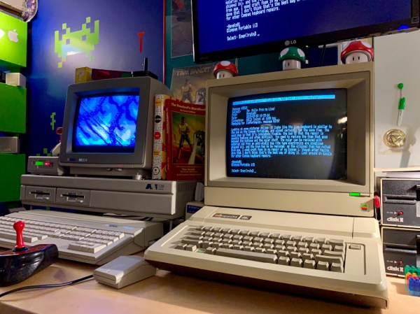
Blinkenlights To Bootloader: A Guide To STM32 Development

While things like the Arduino platform certainly opened up the gates of microcontroller programming to a much wider audience, it can also be limiting in some ways. The Arduino IDE, for example, abstracts away plenty of the underlying machinations of the hardware, and the vast amount of libraries can contribute to this effect as well. It’s not a problem if you just need a project to get up and running, in fact, that’s one of its greatest strengths. But for understanding the underlying hardware we’d recommend taking a look at something like this video series on the STM32 platform.

The series comes to us from [Francis Stokes] of Low Byte Productions who has produced eighteen videos for working with the STM32 Cortex-M4 microcontroller. The videos start by getting a developer environment up and blinking LEDs, and then move on to using peripherals for more complex tasks. The project then moves on to more advanced topics and divides into two parts, the development of an application and also a bootloader. The bootloader begins relatively simply, and then goes on to get more and more features built into it. It eventually can validate and update firmware, and includes cryptographic signing (although [Francis] notes that you probably shouldn’t use this feature for production).

One of the primary goals for [Francis], apart from the actual coding and development, was to liven up a subject matter that is often seen as dry, which we think was accomplished quite well. A number of future videos are planned as well. But, if you’re not convinced that the STM32 platform is the correct choice for you, we did publish a feature a while back outlining a few other choices that might provide some other options to consider.

Continue reading “Blinkenlights To Bootloader: A Guide To STM32 Development”

All About USB-C: Connector Mechanics

There’s two cases when hackers have to think about USB-C connector mechanics. The first is when a USB-C connector physically breaks, and the second is when we need to put a connector on our own board. Let’s go through both of them.

Clean That Connector

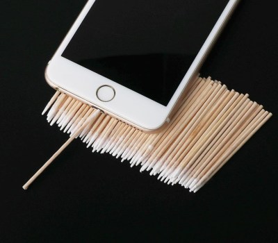
What if a socket on your phone or laptop fails? First off, it could be due to dust or debris. There’s swabs you can buy to clean a USB-C connector; perhaps adding some isopropyl alcohol or other cleaning-suitable liquids, you can get to a “good enough” state. You can also reflow pins on your connector, equipped with hot air or a sharp soldering iron tip, as well as some flux – when it comes to mechanical failures, this tends to remedy them, even for a short period of time.

How could a connector fail, exactly? Well, one of the pins could break off inside the plastic, or just get too dirty to make contact. Consider a device with a USB-C charging and data socket, with USB 2.0 but without high-speed pairs – which is to say, sadly, the majority of the phones out there. Try plugging it into a USB-A charger using a USB-A to USB-C cable. Does it charge, even if slowly? Then, your VBUS pins are okay.

Plug it into a Type-C charger using a Type-C cable, and now the CC pins are involved. Does it charge in both orientations? Then both of your CC pins are okay. Does it charge in only one orientation? One of the CC pins has to be busted. Then, you can check USB 2.0 pins, used for data transfer and legacy charging. Plug the phone into a computer using a USB-A to USB-C cable. Does it enumerate as a device? Does it enumerate in both orientations? If not, you might want to clean D- and D+ pins specifically, maybe even both sets. Continue reading “All About USB-C: Connector Mechanics”

A Handy Guide To The Humble BBS

Some of us who’ve been online since the early days fondly remember the web of yore — with its flashing banners, wildly distracting backgrounds, and automatic side-scrolling text. But there was a time before the worldwide web and the Internet as we recognize it today, and the way of communicating in this before-time was through Bulletin Board Systems, or BBS. There are still some who can cite this deep magic today, and this page is perhaps the definitive guide to this style of retrocomputing.

This how-to is managed by [Blake.Patterson] who is using a wide variety of antique machines and some modern hardware in order to access the BBSes still in service. He notes in this guide that it’s possible to use telnet and a modern computer to access them, but using something like an Amiga or Atari will give you the full experience. There are some tools that convert the telephone modem signals from that original hardware to something that modern networking equipment can understand, and while the experience might be slightly faster as a result, it does seem to preserve the nostalgia factor quite well.

For those looking for more specific guides, we’ve featured [Blake]’s work a few times in the past, once with an antique Epson PX-8 laptop and again with a modern ESP8266. It doesn’t take much computing power to get connected to these old services, so grab whatever you can and start BBSing!

A Builders Guide For The Perfect Solid-State Tesla Coil

[Zach Armstrong] presents for your viewing pleasure a simple guide to building a solid-state Tesla coil. The design is based around a self-resonant setup using the UCC2742x gate driver IC, which is used in a transformer-coupled full-wave configuration for delivering maximum power from the line input. The self-resonant bit is implemented by using a small antenna nearby the coil to pick up the EM field, and by suitably clamping and squaring it up, it is fed back into the gate driver to close the feedback loop. Such a setup within reason allows the circuit to oscillate with a wide range of Tesla coil designs, and track any small changes, minimizing the need for fiddly manual tuning that is the usual path you follow building these things.

Since the primary is driven with IGBTs, bigger is better. If the coil is too small, the resonant frequency would surpass the recommended 400 kHz, which could damage the IGBTs since they can’t switch much faster with the relatively large currents needed. An important part of designing Tesla coil driver circuits is matching the primary coil to the driver. You could do worse than checkout JavaTC to help with the calculations, as this is an area of the design where mistakes often result in destructive failure. The secondary coil design is simpler, where a little experimentation is needed to get the appropriate degree of coil coupling. Too much coupling is unhelpful, as you’ll just get breakdown between the two sides. Too little coupling and efficiency is compromised. This is why you often see a Tesla coil with a sizeable gap between the primary and secondary coils. There is a science to this magic!

Pretty Lithium Carbonate plasma

A 555 timer wired to produce adjustable pulses feeds into the driver enable to allow easily changing the discharge properties. This enables it to produce discharges that look a bit like a Van De Graaff discharge at one extreme, and produce some lovely plasma ‘fire’ at the other.

We’ve covered Tesla coils from many angles over the years, recently this plasma tweeter made sweet sounds, and somehow we missed an insanely dangerous Tesla build by [StyroPyro] just checkout that rotary spark gap – from a distance.

Continue reading “A Builders Guide For The Perfect Solid-State Tesla Coil”

Four Years Of Learning ESP8266 Development Went Into This Guide

The ESP8266 is a great processor for a lot of projects needing a small microcontroller and Wi-Fi, all for a reasonable price and in some pretty small form factors. [Simon] used one to build a garage door opener. This project isn’t really about his garage door opener based on a cheap WiFi-enabled chip, though. It’s about the four year process he went through to learn how to develop on these chips, and luckily he wrote a guide that anyone can use so that we don’t make the same mistakes he did.

The guide starts by suggesting which specific products are the easiest to use, and then moves on to some “best practices” for using these devices (with which we can’t argue much), before going through some example code. The most valuable parts of this guide especially for anyone starting out with these chips are the section which details how to get the web server up and running, and the best practices for developing HTML code for the tiny device (hint: develop somewhere else).

[Simon] also makes extensive use of the Chrome developers tools when building the HTML for the ESP. This is a handy trick even outside of ESP8266 development which might be useful for other tasks as well. Even though most of the guide won’t be new to anyone with experience with these boards, there are a few gems within it like this one that might help in other unrelated projects. It’s a good read and goes into a lot of detail about more than just the ESP chips. If you just want to open your garage door, though, you have lots of options.

A Guide For Driving LED Matrices

Building an LED matrix is a fun project, but it can be a bit of a pain. Usually it starts with hand-soldering individual LEDs and resistors together, then hooking them up to rows and columns so they can be driven by a microcontroller of some sort. That’s a lot of tedious work, but you can order an LED matrix pre-built to save some time and headache. You’ll still need a driver though, and while building one yourself can be rewarding there are many pitfalls and trade-offs to consider when undertaking that project as well. Or, you can consider one of a number of drivers that [deshipu] has outlined in detail.

The hangups surrounding the driver board generally revolve around the issue of getting constant brightness from LEDs regardless of how many in the row or column are illuminated at one time. Since they are typically driven one row or column at a time, the more that are on the lower the brightness each LED will have. Driver boards take different approaches to solving this problem, which usually involve a combination of high-speed scanning of the matrix or using a constant-current source in order to eliminate the need for resistors. [deshipu] outlines four popular chips that achieve these purposes, and he highlights their pros and cons to help anyone looking to build something like this.

Most of these boards will get you to an 8×8 LED matrix with no problem, with a few going a few pixels higher in either direction. That might be enough for most of our needs, but for something larger you’ll need other solutions like the one found in this 64×32 LED matrix clock. There are also even more complicated drivers if you go into extra dimensions.

Photo credit: Komatta [Public domain], from Wikimedia Commons

A QR Code, Step By Step

We should all be familiar with QR codes, those blocky printed patterns containing encoded text, URLs, or other data. A few years ago they were subject to their own cloud of hype, but now they have settled down in their niche of providing a handy route for a smartphone owner to reach a website without having to type an address.

Have you ever wondered how they work? There are plenty of dry technical guides out there, but if they’re not your thing you might find [Nayuki]’s step-by-step guide to be of interest. It explains the encoding and error checking bit generation process before starting on the familiar three-squares pattern and timing bars of the QR code itself. The really interesting part comes with its explanation of overlays, a set of repeating patterns that are added to the final data segment, and how the pattern used is chosen to minimise penalties due to large blocks of the same colour in the final piece. The chances are most of us will never have to create a QR code from scratch, but it is this type of fascinating technical general knowledge that makes guides like this such an interesting read.

QR codes have appeared in quite a few projects here over the years, but the one we find particularly amusing is this project to hack them by changing one QR into another.

Via Hacker News.