[Michael Ossmann] spoke on Friday to a packed house in the wireless hacking village at DEF CON 25. There’s still a day and a half of talks remaining but it will be hard for anything to unseat his Reverse Engineering Direct Sequence Spread Spectrum (DSSS) talk as my favorite of the con.
DSSS is a technique used to transmit reliable data where low signal strength and high noise are likely. It’s used in GPS communications where the signal received from a satellite is often far too small for you to detect visually on a waterfall display. Yet we know that data is being received and decoded by every cell phone on the planet. It is also used for WiFi management packets, ZigBee, and found in proprietary systems especially any dealing with satellite communications.
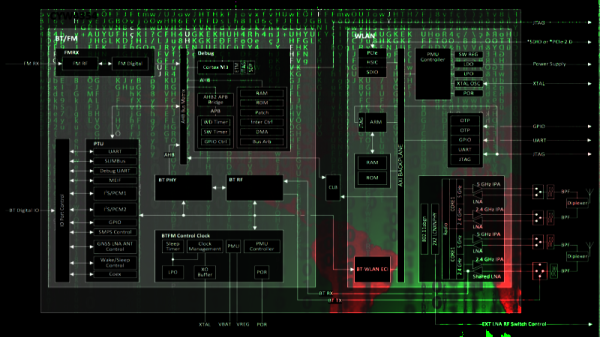
[Michael] really pulled a rabbit out of a hat with his demos which detected the DSSS signal parameters in what appeared to be nothing but noise. You can see below the signal with and without noise; the latter is completely indiscernible as a signal at all to the eye, but can be detected using his techniques.

Strong DSSS Signal, no noise

Same DSSS signal not apparent
Detecting DSSS with Simple Math
 [Michael] mentioned simple math tricks, and he wasn’t kidding. It’s easy to assume that someone as experienced in RF as he would have a different definition of ‘simple’ than we would. But truly, he’s using multiplication and subtraction to do an awful lot.
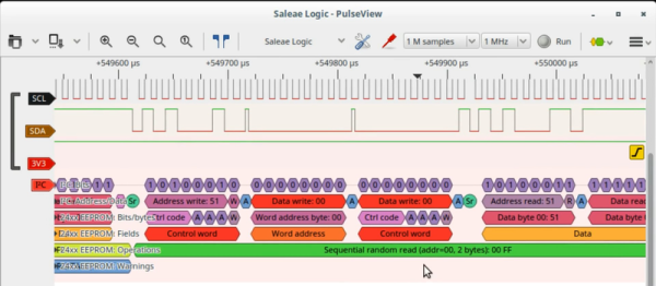
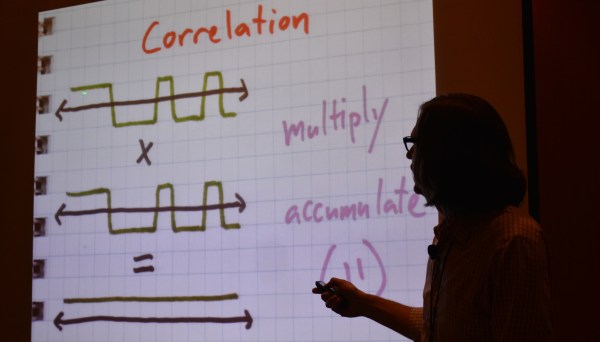
DSSS transmits binary values as a set called a chip. The chip for digital 1 might be 11100010010 with the digital 0 being the inverse of that. You can see this in the slide at the top of this article. Normal DSSS decoding compares the signal to expected values, using a correlation algorithm that multiplies the two and gives a score. If the score is high enough, 11 in this example, then a bit has been detected.
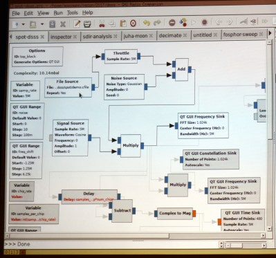
To reverse engineer this it is necessary to center on the correct frequency and then detect the chip encoding. GNU radio is the tool of choice for processing a DSSS capture from a SPOT Connect module designed to push simple messages to a satellite communication network. The first math trick is to multiply the signal by itself and then look at spectrum analysis to see if there is a noticeable spike indicating the center of the frequency. This can then be adjusted with an offset and smaller spikes on either side will be observed.
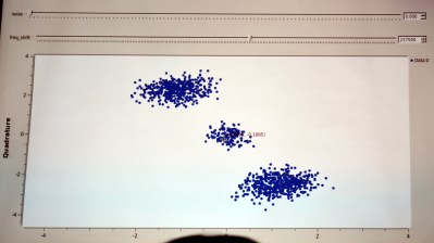 When visualized in a constellation view you begin to observe a center and two opposite clusters. The next math trick is to square the signal (multiply it by itself) and it will join those opposite clusters onto one side. What this accomplishes is a strong periodic component (the cycle from the center to the cluster and back again) which reveals the chip rate.
Detecting symbols within the chip is another math trick. Subtract each successive value in the signal from the last and you will mostly end up with zero (high signal minus high signal is zero, etc). But every time the signal spikes you’re looking at a transition point and the visualization begins to look like logic traced out on an oscilloscope. This technique can deal with small amounts of noise but becomes more robust with a bit of filtering.
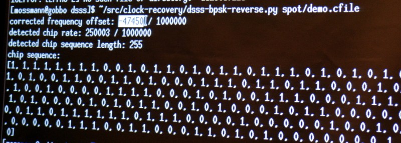
This sort of exploration of the signal is both fun and interesting. But if you want to actually get some work done you need a tool. [Michael] built his own in the form of a python script that cobbles up a .cfile and spits out the frequency offset, chip rate, chip sequence length, and decoded chip sequence.
Running his sample file through with increasing levels of noise added, the script was rock solid on detecting the parameters of the signal. Interestingly, it is even measuring the 3 parts per million difference between the transmitter and receiver clocks in the detected chip rate value. What isn’t rock solid is the actual bit information, which begins to degrade as the noise is increased. But just establishing the parameters of the protocol being used is the biggest part of the battle and this is a dependable solution for doing that quickly and automatically.
You can give the script a try. It is part of [Michael’s] Clock Recovery repo. This talk was recorded and you should add it to your reminder list for after the con when talks begin to be published. To hold you over until then, we suggest you take a look at his RF Design workshop from the 2015 Hackaday Superconference.


 The
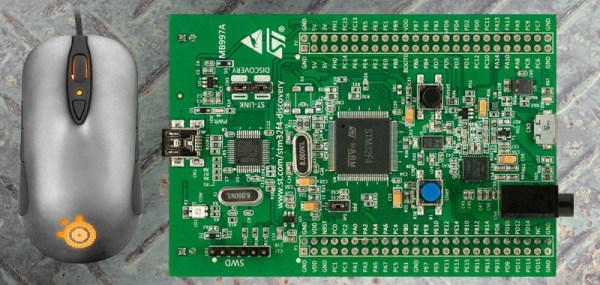
The 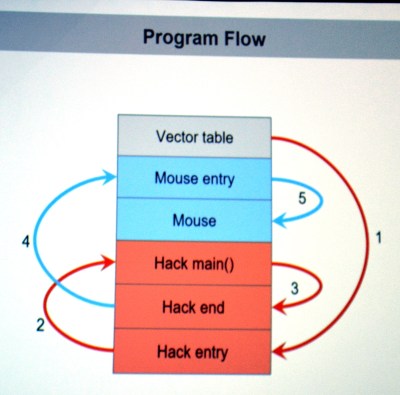 They first looked through the binary for a large block of zero values signifying unused space in flash. The injected firmware is designed to enumerate as a USB keyboard, open Notepad, then type out, save, and execute a PowerShell script before throwing back to the stock firmware (ensuring the mouse would still function as a mouse). Basically, this builds a