[Daqq] is back at it again with the linear algebra, and he’s now come up with a method for determining the resistance of lots of resistors using little of wires and loads of math.
Like any reasonable person, [daqq] decided it would be fun to “solve one of those nasty [electrical engineering] puzzles/exercises where you start out with a horrible mess of wires and resistors and you are supposed to calculate the resistance between two nodes.” You know, just an average Saturday night. At the time, he was also fascinated by Charlieplexing – an awesome technique that either allows one to control multiple polarized components, such as LEDs, simply by connecting them in a specific way. After toying with the idea for a while, [daqq] found that using just Charlieplexing would be“a horrible mess” but he didn’t stop there. Drawing inspiration from Charlieplexing, he came up with the idea to connect things in such a way that every node is connected by one connection to every other node – a complete graph from a topological view point (this makes so much more sense visually). From here, he was able to set pins to HIGH, LOW, or INPUT and gather all the data needed to solve his linear system of equations.
Now, there is a balance to everything, and while this system can determine the resistance of .5*N(N-1) resistors using just N wires, it also a memory and computation hungry method. Oh well, can’t have it all. But, while it’s computationally hungry, [daqq] got it working on an ATMega32, so it’s not an unmanageable feat. And, let’s not forget to mention [daqq’s] wonderful writing. Even if you don’t know linear algebra (or would rather forget), it’s a good read from a theory perspective. So good, in fact, that [daqq] is getting published in Circuit Cellar!
We love to see theory in the hacker world, so keep it coming! But, while we wait (wink wink), there’s always time to review the basic Hacker Calculus and check out our past math-related articles.


Thank you for the mention :) A bit of a correction – the ATMega32 is used only as the measurement system – it pretty much just sets the GPIOs, measures the voltages and sends the data to the computer – that will be in part 3 of the text. The actual number crunching is done on a real computer – that will be in part 4 :) Neither of these parts are finished yet, I’m working on them :)
Thanks for the mention!
Could you explain why “using just Charlieplexing would be ‘a horrible mess'” ? That way other people could avoid going that route when using the same set of constraints and hypothesis as you did.
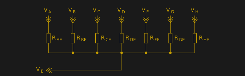
From the schematic above, you could set Va HIGH and the rest as INPUT (High-Z), then you could measure Ra, and so on, but since that is trivial and not “a horrible mess”, I guess that you had roadblocks, hence the need to understand initial conditions and constraints that led to your work.
Good question.
First of all, setting all nodes as input (or high) will not yield any data at all – setting everything to one potential only means that you’ll get the same voltage value on all of the nodes.
Note that the schematic given in the hackaday article is a simplification that arises when ALL of the nodes except one are connected to a source and the E node is hi-Z. To every single node there are (assuming 8 nodes) 7 connections, each with its own resistor (see http://www.daqq.eu/wp-content/uploads/2017/01/g5970.png ), for a total of 28 resistors on an 8 node system.
A simple charlieplexing-ish measurement does allow you to measure a few resistors, that are directly connected to a node with multiple known resistors, tough it gets nasty. For the rest you need to create a set of equations, where you divide very small numbers with very small numbers, both of which have noise. The more resistors away from known resistors you get, the greater BS numbers you get.
I’ll probably add a bit in the text on why it’s not good with the specifics.
Neat idea. The title image for this blog entry is a bit misleading, because first I thought, ok, one more pin and one more known resistor and you could do this more easily. But for e.g. N=16 it would be 120 resistors, which looks useful.
But why do you need a computer to solve the linear equations? Implementing a simple Gaussian Elimination algorithm is trivial with the ATMega32, and even with floating point numbers very fast, if it is not too big.
Hi Frank,
From my understanding, Gaussian elimination works properly only for noise free matrices that “fit” from all sides, essentially trying to reduce the system of linear equations until it comes to one row where it can find, say, G15 = 0.0144 and reversly fit that G15 into another equation and so forth… This would not work, since the data coming from the ADC is inherently noisy and basing all of the equations on a wrong-ish result just gives you more wrong(er) results. Also, the resistances change slightly (since that is the point of the measurement), meaning that one part of the matrix will deal with a different value of the same resistor that the final measurement. I’ve tried going down a similar path, it does not work properly, much better results are gained by iterative solving means because they take into account all of the equations (measurement results) at the same time, which simply yields better results.
Also, an ATMega32 has 2kB SRAM. Even a small measurement matrix (floats, 28 unknowns, 260 equations) would be around ~30kB big (assuming dense matrix formating, a sparse matrix *might* just barely fit).
If you wish to discuss this in more detail, I invite you to use the eevblog forum topic for this ( http://www.eevblog.com/forum/metrology/measuring-lots-of-resistors-using-very-few-signals-a-new-method!/ ) , where the discussion tools are somewhat better. I will of course try to reply here as well :-)
Best regards,
David
Eevblog has some moderators with big egos that have banned people for comments that the HaD folks wouldn’t take a second look at.
I’ve had the opposite experience.
Although HaD is simply a content aggregator capitalizing on the backs of original content producers, their writers and moderators act as bad as the anonymous drive-by troll commenters.
Critical comments, even when politely pointing out gross inaccuracies, are typically deleted or downplayed with far too much attitude.
EEVblog has plenty of asshats, but definitely more forbearing. My first three posts called out a moderator for flat out lying about an electrical measurement (over-unity), zero punishment.
I told Brain Pinchoff that Open Source is simply a liability for hardware startups and I’m IP blocked.
RE: SAM: You weren’t IP blocked.
It might work with some dynamically calculated error ignore limit. But you are right, maybe not the best method and iterate solving is better. I guess because the linear equation system is overdetermined, this can actually increase the accuracy if you use this fact and numbers?
And 2 k RAM is really low, I forgot how limited these Arduino CPUs are. Maybe use one of the STM32F4 CPUs: there are ones with 64 kB RAM and hardware floating point, running at 168 MHz, and still not too expensive (I have a STM32F4 Discovery kit for testing). Or an ESP32: It has not only WiFi, but it is also a very powerful CPU, running at 240 MHz and even 520 KB RAM. With this a a nice standalone solution would be possible for all kind of applications. But the STM32F4 family might be faster for lots of floating point calculations:
https://blog.classycode.com/esp32-floating-point-performance-6e9f6f567a69
Frank, I am aware of how powerful microcontrollers are available for peanuts :-) The point of the demo was to demonstrate that the math can be done. It’s simply easier to implement and experiment on a PC than a micro. That said, I’m sure it’s possible to do it on a micro – I have never claimed otherwise.
As to the math, yes, being overdetermined and using an iterative solver increases the accuracy – basically, it’s the only thing that can get the numbers out of there with a relatively low error :-)
There’s an example compiled matrix available in the text in part two. If you wish to run it through your system, you can.
How about a Simplex? That would be cool.
Normally I would think the noise in ADC readings can be determined and either do some averaging or drop some bits. But, you have a lot of equations and the more you multiply, the wider the noise band gets. 16 sets of readings should reduce noise by 2 bits, shouldn’t it? Have you placed a limit on how much time can be spent taking readings?
How would you implement the linear system solving algorithm in the ATMega32? Gauss Seidel?
See pseudo code here:
https://en.wikipedia.org/wiki/Gaussian_elimination
I’ve implemented this once in Java. As the Wikipedia article says, not the fastest, but very easy to implement and reliable.
You should definitey try Gauss-Seidel. It’s literally 10 lines in matlab/octave and does not use as much memory as Gaussian Elimination (GE), although it is an iterative algorithm and its accuracy depend on the number of iterations (unlike GE)
However, for a small matrix and provided you have enough memory, I guess it’s fine to use GE.
wouldnt it be easily to use a matrix of resistors?
If you mean a grid then no. First of all, this is a more efficient use of wires. Second, while a matrix may seem simpler, there is still the problem of all or the resistors influencing all of the other resistors. It seems simpler, but it’s not – you either have to add a switch between every resistor, or do even nastier math.