Transistors are no doubt one of humankinds greatest inventions. However, the associated greatness brings with it unprecedented complexity under the hood. To fully understand how a transistor works, one needs to be familiar with some Quantum Mechanics! As perhaps any EE undergraduate would tell you, one of the hardest subject to fathom is in fact semiconductor physics.

A good place to start to comprehend anything complex is by having an accurate but most importantly, tangible model at hand. Semiconductors are hard enough to describe with elaborate mathematical tools, is a physical model too much to ask?
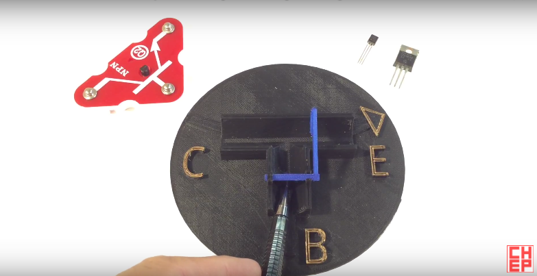
[Chuck] has designed, printed and explained the workings of a BJT transistor using a 3D printed model. We really like this model because it goes a long way to shed light on some of the more subtle features of BJT transistors for beginners.
For example, the simplest “electronic switch” model completely ignores the application of a transistor as a linear amplifier and cannot be used to explain important transistor parameters such as hfe (DC current gain Beta) or the VBE (voltage to forward bias the base-emitter junction). [Chuck’s] model on the other hand certainly offers better intuition on these, as the former can be linked to the length of the levers arm and the latter to the minimum force needed to rotate the lever. The Tee structure even signifies the combination of base current with the collector current during operation!
If physical models are not your thing, the classic pictorial depiction, the “Transistor Man” in the Art of Electronics might be of interest. If you’ve even outgrown that, its time to dig into the quantum mechanics involved.


Oh man.. I have so got to finish assembling my 3d printer!!!
Thanks for posting my video.
great analogy- in my opinion water is one of the best and easiest to understand analogies to electric current- just like an electric car- particles pour in to charge it, and leave the battery through the motor. I think there is a feeling that science and physics should be left in the hands of experts and are too complicated for average people- an effort to “lose the public” when it comes to science and technology.
It’s not a great analogy.
It’s constructed completely wrong. The flap for the base-emitter path should be piped to the -other- side of the collector-emitter flap. If you think of what would happen if this was an actual hydraulic or pneumatic system, the pressure from the collector tube would simply push the base flap closed and you’d need to have more pressure (voltage) on the base than your collector to open the transistor. This is not how a transistor behaves.
Instead of a T junction, there should be a separate parallel tube from base to emitter.
The fix is very easy though. Just swap the collector and emitter, and it works like a transistor should work.
It’s easy to see how it won’t work in this configuration. Suppose the transistor is closed and you have a “battery” that gives 10 psi on the collector. How much pressure do you need on the base then to turn the base flap open? More than 10 psi, but you ain’t got more than 10 psi, so your transistor cannot be opened.
If we’re pretending that 1 psi is 1 volts, a proper transistor would have a backpressure of about 0.6 psi against the base flap, and for that it would need a separate tube to the emitter which is presumably at 0 psi, and a spring that buckles at 0.6 psi pressure. Anything above 0.6 psi at the base would start opening the collector-emitter flap, and anything below would close it.
“Mathematical equations governing the various currents inside a BJT”. I think they describe the currents. An equation can be used to govern your stock buys and sells. ITNOA
WOW, a PNP and NPN ,all in one component. Kudos !
Very well done. This is an excellent learning tool.
Certainly better than my “using a game engine” idea.
It’s exceptionally hard to actually show a sensible, macroscale physical model of a bipolar transistor that’s anything like how it functions physically. It’s a fluke of nature that these were invented before MOSFETs and easier to produce – thus resulting in better commercial avilability of discrete BJTs today for hobbyists, which is partly why they’re still used so often in basic circuits.
A critical part of the function of a BJT is that you are working in a size regime where characteristic diffusion lengths are longer than the actual length of the doped channels. If your model cannot model this, you probably are not modeling how a BJT functions at all. There probably exists a fluidic analogy – but similarly, diffusion scales for liquids are going to be on a microscale as well – so I actually can’t think of any good macroscale phenomena that works anything like a BJT. Really, the function doesn’t make a lot of sense with any physical analog, I’d think.
FETs are much easier. The “gate” model that was shown in this video is pretty much spot on. Drift is far more intuitive than diffusion.