How many remote controls do you have in your home? Don’t you wish all these things were better integrated somehow, or that you could add remote control functionality to a random device? It’s a common starting point for a project, and a good learning experience for beginners.
A common solution we’ve seen applied is to connect a relay in parallel to all the buttons we want to press. When the relay is triggered, for example by your choice of microcontroller, it gets treated as a button press. While it does work, relays are not really the ideal solution for the very low current loads that we’re dealing with in these situations.
As it turns out, there are a few simple ways to solve this problem. In this article, we’re going to focus on using common bipolar junction transistors instead of relays to replace physical switches. In short, how to add transistors to existing electronics to control them in new ways.
Relays
Relays are still a good solution in some situations. When you’re dealing with high power, or when you need something exactly electrically identical to a closed switch, relays are a reasonable choice. Ever wonder why your USB digital storage oscilloscope makes clicking noises? Those are relays switching between the different modes of the scope – this preserves signal integrity.
On the other hand, relays are typically large, expensive, slow, require significant power, add a large coil of wire to the circuit (this can introduce a lot of noise), and have mechanical parts that are prone to failure. Solid state relays do exist and address some of these issues, but are not particularly cheap.
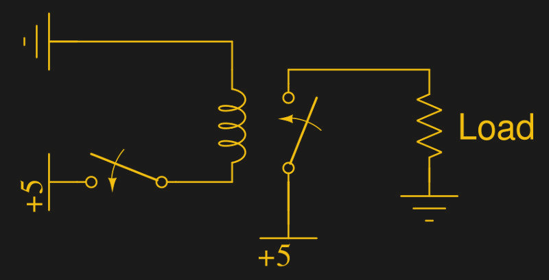
When a current is supplied to the coil of wire, the relay closes, allowing current to pass. In reality a transistor is generally added to the circuit to provide enough power to control the relay, while a diode protects the transistor from the reverse voltage spike caused by cutting power to the relay (the energy stored in the magnetic field of the coil has to go somewhere!). If the relay is attached parallel to a switch in some external device (such as a remote control), closing the relay is like closing the switch.
Bipolar Junction Transistors (BJT)
BJTs are a very common type of transistor. Their function is to amplify current. If a quick overview of how they work would be useful before continuing, this short guide may help.
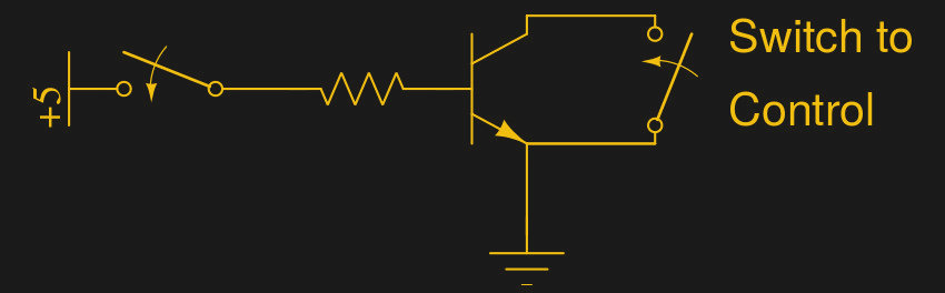
A small current between the base and emitter controls a much larger current between the collector and emitter. If the collector and emitter are placed in parallel to an open switch, then the state of that switch can be easily controlled by a microcontroller output pin.
Transistors want current control, and your microcontroller GPIOs attempt to put out a given voltage. You need a voltage-to-current transformer, otherwise known as a resistor. (See Ohm’s law.) The exact value will vary, but 10 kΩ is a good starting point for replacing pushbuttons. A simple test circuit (using a switch to provide the current needed instead of a microcontroller) may look something like this:
If you were to take a multimeter and measure the resistance across the transistor from the collector to the emitter, it would drop from open-circuit to near zero when a current is provided between the base and emitter. In reality, there’s a voltage drop between the collector and emitter (about 0.3 volts, but it depends on the transistor) when the BJT is ‘switched on’ but for our purposes it is sufficient to think of it as going from infinite resistance to zero.
A reasonable choice of BJT is the venerable 2N2222. It’s available worldwide, is very inexpensive, reasonably fast, and can dissipate up to 500 milliwatts of power which is more than sufficient in this case. Most NPN-type BJTs will work fine though.
Specific Use Case
Consider the following alarmingly pink battery-powered external speaker/radio. It once had an infrared remote, now lost. It’s not a high quality device, but could be marginally useful again if there was a convenient way of turning it on:
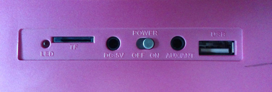
Our first step is to disassemble it, and determine which pins of the ‘on’ switch need to be connected to activate the device:
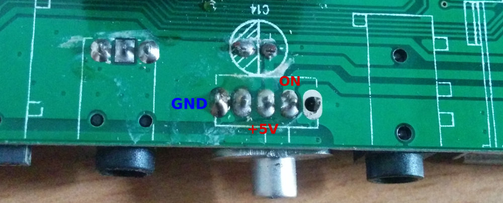
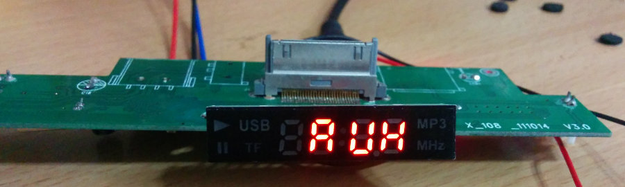
When the device is powered and the switch set to ‘on’, we see 5 V relative to ground on two pins. When the device is powered off, only one of those pins is at 5 V. We start by soldering wires to those pins, applying power to the device, and crossing the wires. The device turned on, and by default switched to Aux mode. How convenient!
Now that we’ve isolated which pins of the switch need to be connected, we can breadboard a quick circuit with out BJT based switch controller and test it out.
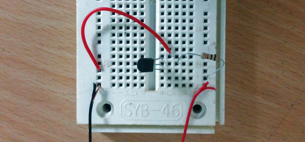
When the right lead of the resistor is connected to power, the resistance across the collector/emitter drops to zero when measured by a multimeter. If it drops, but not quite to zero, you may have your transistor in backwards.
Since this worked, it’s time to solder it to perfboard and connect it to a microcontroller, in this case an ESP8266 mini-D1 board. Instead of connecting the transistor base to power, we will connect it to one of the mini-D1 output pins (we chose D0).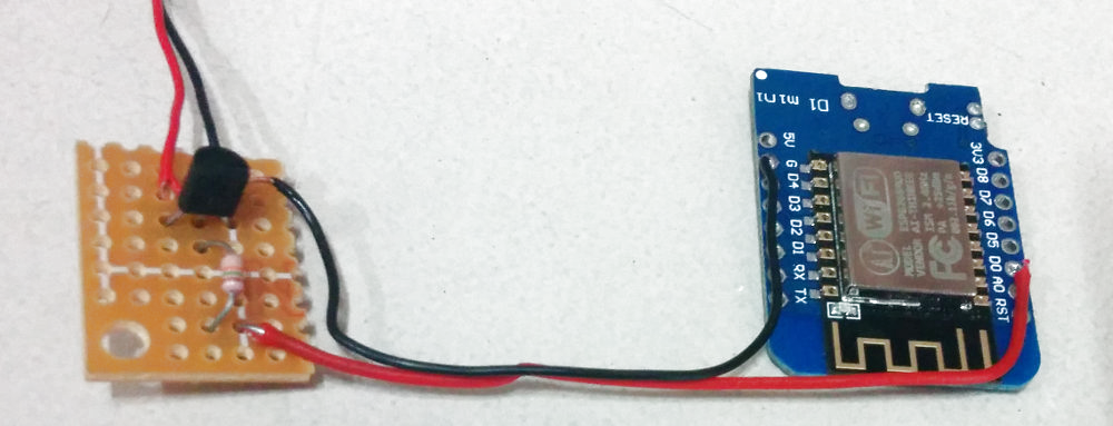
In this case, the firmware causes the ESP8266 to raise pin D0 high when it receives a certain UDP network packet from an Android smartphone application. If we wanted to control all features of the speakers, we would have to repeat this process for each switch. It’s admittedly not as elegant a solution as reverse engineering the IR protocol, but it’s versatile, fast enough to be an afternoon project without needing a ton of experience, and it works quite well.
Congratulations – you now have the most basic IoT device: an Internet connected switch. Before you go wild, you may want to consider adding some security depending what you’re connecting.
Also note this approach has some shortcomings. Not all switches function by simple electrical contact: some relatively common switches rely on a change in capacitance. Also in high noise environments, it’s possible for a BJT to unexpectedly trigger, although this can be minimized by placing the base resistor as close as reasonably possible to the transistor base, and if necessary by adding a small grounded metal enclosure (a Faraday cage) around the BJT and nearby traces. Finally, when a BJT fails due to overheating, they often create a short. In other words, be mindful of the consequences of your control system failing.


Would like to see the limitations on the transistor based approach expanded on a bit. Standby / parasitic current draw, etc.
having to share ground, no galvanic isolation, what if the switch you’re replacing is on the high side of te circuit…
Optocoupler would be better solution in all those cases, when isolation from common ground is necessary. I’d also use N-MOSFETs because their Rdson is closer to switch resistance than voltage drop of NPN transistors.
Using a MOSFET is overkill for signal switches.
I used this kind of BJT arrangement to trigger garage door openers. Thankfully I didn’t need to isolate the signal common.
What if switches are connected to lower voltage than usual 5V? Then voltage drop across BJT might be too big to trigger logic low on input. Also one of the tricks sometimes used to reduce number of pins is to use resistors to form voltage divider with buttons – BJT won’t work in that case…
I don’t think the BJT voltage drop would be so bad. A 2N3904 can saturate to around 0.05V with collector current under 10mA and 1mA base current. I just think that for generic signal switches you can just use jellybean parts
In that case (voltage dividers) you mostly need optocouplers. If you do not have >10 buttons on a divider string, the small voltage drop of the BJT in the optocoupler normally doesn’t matter
You can do it without optocouplers, but then you need MOSFETs and an elevated gate voltage. In the case of a voltage divider chain the base current of a BJT will probably disturb the levels. The gate drive voltage must be higher than the sum of the working voltage of the circuit and the gate-threshold voltage of the used MOSFET. If the circuit to-be-controlled runs on 3,3V and you get low-V_g_th MOSFETs with a threshold of <1,5V then you can do it with 5V on your control circuit. If you want to control a 5V circuit you need something like 8V for the gates and some level shifters.
You connect the MOSFET across the buttons at the voltage divider and connect it's gate to 0V. To simulate the button press you connect it to 8V. Then it conducts independent of the actual voltage (below 5V) on the button.
for me a N-MOSFET 2n7000 or 2n7002 is very inexpensive and logic level but I also think that an optocoupler might be the way to go here
Agreed on both points. And with relatively inexpensive components like the 30N06L, even higher-power (30 A for this part) applications are possible.
Out of curiosity, why suggest the 2N2222 as the default? The 2N3904 is far more commonly available today, is considerably cheaper ($0.19 in singles on DigiKey compared to $2.23), is comparable in operating voltage and power dissipation (even a little better), and a little bit faster. The only place the 2N2222 beats the 2N3904 is in the max rated collector current, but at 200 mA, the 2N3904 should be fine in most cases today. So why the 2N2222?
Because 2N2222 is common in cheap computer PSUs. Especially those from black list of power supplies. I have few from Modecoms Feel 300-350W PSUs…
Most people aren’t buying old power supplies to source their components. And if they are… again, I’ll point to $0.19 in singles. How much for a power supply with maybe a few 2N2222’s in it?
I’ve got box of them for free. Most of them have only 1-3 dead capacitors only. I usually take them apart for inductors and transformers, power transistors and diodes, TL431s, etc. Free fans and cables are useful too. Today I made a ringing choke converter and only new parts were two capacitors and two sets of goldpins…
You can take most references to a 2N2222, a BC547, a 2N3904 as “Anything you can find in your junkbox that looks somewhat like an NPN transistor, and things will work fine.
All the more reason to point to the 2N3904 in the article. People who don’t have a junkbox and are looking to fill it probably would be better off not going for the 2N2222.
If you really want the higher current, in reading up on this topic to try to understand the appeal of the old 2N2222 I came across the 2N4401. Almost identical specs to the 2N2222 and sold at $0.25 a piece.
About the only thing I can think of as to why the 2N2222 keeps coming up is because it’s what’s cited in the mass of old tutorials. We really need to help people get away from the old, obsolete parts because they’re more expensive and often not as good as components that are easily sourced today. How about the 1N34, for example, which shows up in amateur radio tutorials everywhere? Anywhere you feel safe it’s not counterfeit it’s insanely expensive.
Here everyone uses 2N3055 to build amps and workbench supplies, everyone uses that crappy Electronics Labs supply circuit and hey are too lazy or too stupid t look for better alternatives…
And for 1N34, in all cases any germanium diode would work. Pity that not many of them are made…
The 2N3904 is best with collector currents around 10 mA.
The 2N2222 is best with collector currents around 100 mA.
The 2N7000 FET can be substituted, but beware they are not ideal with 3.3 Volt logic, but are okay at 5 Volts.
In all cases, there should be a pull-down resistor on the base. 10 kOhm will do.
The 2n2222 (in the metal can) might be outdated, put the pn2222 (TO-92) part is still readily available for around $0.20 in single quantity. As for reasons to use it, as [Dave Null] mentioned the pn2222 has a higher max collector current than the 2n3904.
Mouser link [ http://www.mouser.com/ProductDetail/ON-Semiconductor-Fairchild/PN2222ATFR/?qs=sGAEpiMZZMtdAabcSkQOl4wFpopiDzZs ]
The short answer is that most Small Signal transistors would work fine so it comes down to what people are familiar with and now days it seems that people are more familiar with component numbers (specifications) they see in old circuits online.
Back in the day we had an annual book that had the specs of almost all transistors available. And we had to have the art of choosing transistors by specification and even to choose alternative substitutes.
Ironically, older engineers still have the art of choosing transistors and so we choose newer devices that have better specs and are more economical while younger EE’s tend to use older parts that they have seen in example circuits.
“while a diode protects the transistor from the reverse voltage spike caused by cutting power to the relay ” – not reverse polarity, current flow the same direction in coil after cutting power to the relay.
the article is correct, and so are you. the decreasing current is still in the same direction, but the voltage spike is in reverse.
At least please don’t draw invalid circuits.
also slightly confusing, normal switches and relay contact looking the same. The coil of the relay doesn’t look like a relay coil at all and there is no real way of knowing what switch belongs to the relay (there are no references in the schematic). Please, if it is too much trouble to make a decent schematic, then don’t bother, this is confusing to those who already know (because they think something special is happening while in reality, it’s really not) and for those who don’t know anything at all they will learn nothing from it or learn it incorrectly.
If drawing a schematic with a relay is so difficult then perhaps you might consider a different kind of article…
At least put the power at the top of your schematic (for positive voltages) and put ground at the bottom and if there are any negative voltages put then even lower. So that you can read the circuit (“flow”) from top to bottom.
And whatever you do… NEVER tilt your labels and most certainly NEVER put them upside down. It isn’t fun reading, tilting your head from left to right in order to be able to read those labels. I assume that this article was written to educate people, so with that in mind, please make the following article a little bit mode educational.
lol Jan
I remember the B/W valve TV days when components at higher voltage were higher up the page.
When the input was always on the left and the output was always on the right.
When there were CRO images at critical points.
Now we have disjointed net-lists instead of schematics. Seriously, how long has it been since you have seen a recent and well drawn schematic.
So while I concur with you Jan, I have nothing more that this thimble of water to pour on the approaching inferno.
:)
I really have only one thing to say here: latching relay. Inexpensive, small, all of the isolation benefits of a relay, nil power (low power to latch or release, zero quiescent). There is a reason they are used in everything from industrial controls to the thermostat on your wall (that runs five to ten years on a single AA cell)
Somewhat disappointed to not see a high side and low side mosfet discussed. With very low RDS-on and decent heat mechanisms, you can drive some serious loads. And the bonus of high side is you don’t need to generate high voltages.
Agreed. A FET is actually closer to a pushbutton than a BJT is (FETs being “resistors” and BJTs being a “voltage drop”). I would have wanted something on the solid-state relay and how it differs from a normal relay.
A “solid-state relay” is basically just a TRIAC connected to an opto-isolator. Or the other way round. For controlling simple high-power loads there’s not much difference.