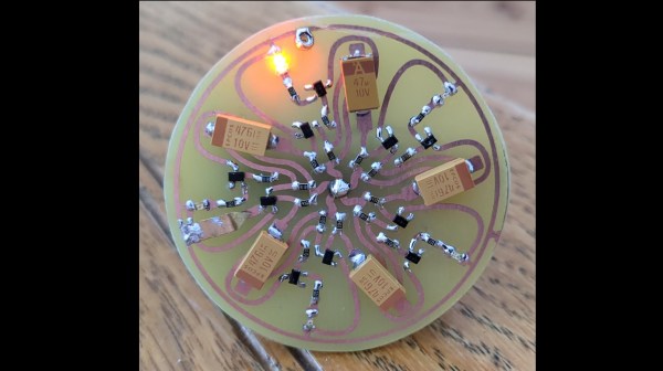
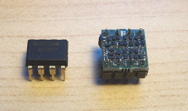
Few electronic ICs can claim to be as famous as the 555 timer. Maybe part of the reason is that the IC doesn’t have a specific function. It has a lot of building blocks that you can use to create timers and many other kinds of circuits. Now [Stoppi] has decided to make a 555 out of discrete components. The resulting IC, as you can see in the video below, won’t win any prizes for diminutive size. But it is fun to see all the circuitry laid bare at the macro level.
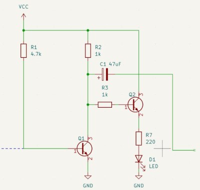
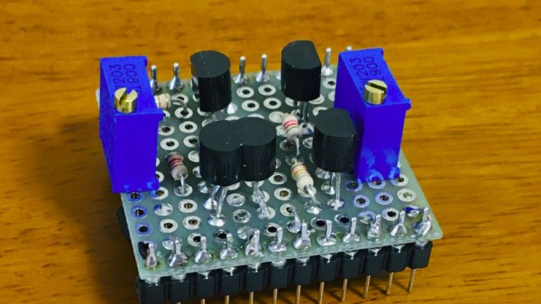
The reality is that the chip doesn’t have much inside. There’s a transistor to discharge the external capacitor, a current source, two comparators, and an RS flip flop. All the hundreds of circuits you can build with those rely on how they are wired together along with a few external components.
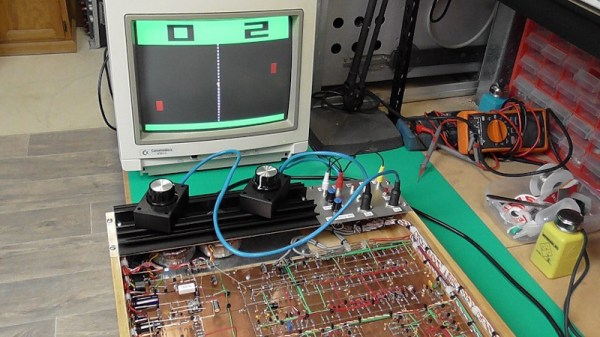
Even on [stoppi]’s page, you can find how to wire the device to be monostable, stable, or generate tones. You can also find circuits to do several time delays. A versatile chip now blown up as big as you are likely to ever need it.
Practical? Probably not, unless you need a 555 with some kind of custom modification. But for understanding the 555, there’s not much like it.
We’ve seen macro 555s before. It is amazing how many things you can do with a 555. Seriously.